1. Introduction to the Noise Floor and Background Hiss
In the rigorous discipline of audio engineering, the pursuit of absolute sonic purity is an elusive objective inherently bounded by the fundamental laws of physics and thermodynamics. The foundational barrier to this pursuit is the "noise floor," defined as the baseline level of unwanted background sound present in any audio or signal system when no intentional signal is running through it. The noise floor represents the ultimate threshold of resolution—a vanishing point in auditory perspective below which the desired audio signal is entirely masked by a dense spectrum of interference. Naim Audio
The noise floor is not a singular, uniform entity but rather a cumulative phenomenon resulting from various interacting systems. It is the aggregate sum of ambient environmental acoustics, electrical interference from local power grids, thermal noise generated within hardware components, and quantization artifacts produced by digital signal processing. In practical application, the noise floor dictates a system's usable dynamic range and its ability to handle weak transient signals. If the baseline noise is excessively high, it will invariably drown out quiet micro-dynamics, rendering the most delicate elements of a recording or broadcast unintelligible. Mastering The Mix

Within this paradigm, "hiss" is widely recognized as one of the most pervasive and challenging manifestations of a high noise floor. Unlike low-frequency electrical hum, which often points to a specific grounding failure, hiss is characterized by high-frequency, broadband white noise that closely resembles the sound of steam escaping a kettle or a pressurized air leak. It is frequently a form of "self-noise" generated internally by the thermal agitation of electrons running through analog circuits, such as those found in microphones, preamplifiers, and magnetic tape machines. In recording environments ranging from high-end commercial studios to critical live sound reinforcements, identifying the precise genesis of background hiss and systematically eliminating it is the hallmark of professional audio engineering. Mastering The Mix
The approach to mitigating this pervasive interference is multi-tiered, requiring a mastery of acoustic environmental control, meticulous electrical power management, rigorous gain staging protocols, and advanced digital signal processing. By understanding the specific origins of various noise artifacts, engineers can implement precise, targeted solutions rather than relying on destructive, broad-stroke filtering that degrades the integrity of the primary audio signal.
2. The Physics and Taxonomy of Audio System Noise
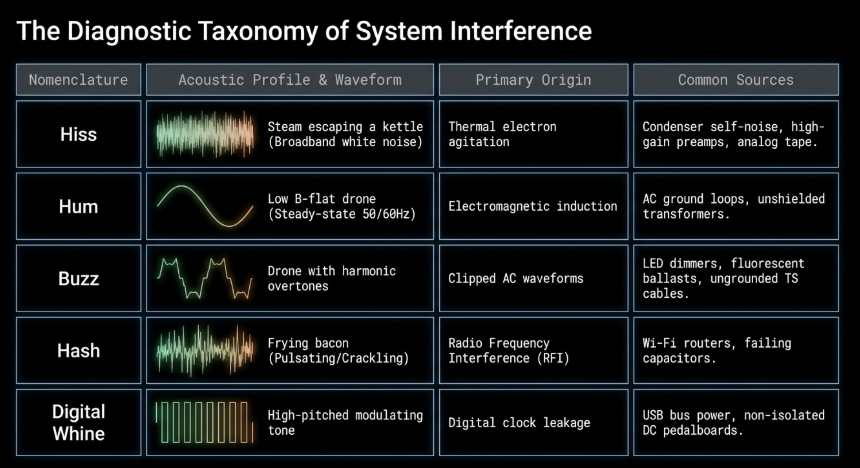
To accurately diagnose a high noise floor, it is strictly necessary to classify the distinct acoustic signatures of system interference. The nomenclature of unwanted noise provides direct diagnostic insight into its physical and electrical origins. The acoustic profile of system noise generally falls into specific categories, each pointing to a different systemic failure, physical limitation, or environmental factor.
Hiss, as previously defined, is almost entirely generated by internal component self-noise. This is mathematically described by the Johnson-Nyquist theorem, which dictates that the thermal agitation of charge carriers (usually electrons) inside an electrical conductor operates independently of any applied voltage. This thermal noise is ever-present in resistors, transistors, and vacuum tubes, establishing an absolute physical limit to how quiet an analog circuit can be. In legacy analog recording paradigms, magnetic tape creates a similar broadband hiss as the randomized magnetic particles slither over the playback heads of a tape recorder, a physical reality that directly catalyzed the development of digital recording formats. Hiss is continuous, steady-state, and rarely originates from external alternating current (AC) power sources. PedalSnake Blog
Conversely, hum is a steady-state, low-frequency oscillation typically occurring at exactly 50 Hz or 60 Hz, depending strictly on regional electrical grid transmission standards. Hum lacks significant harmonic overtones and sounds comparable to a low B-flat played on a bass guitar. This type of noise is almost exclusively the result of AC ground loops or direct electromagnetic interference (EMI) radiating from nearby power transformers or heavy machinery.
When hum contains higher-frequency harmonic overtones, it is classified as buzz. Buzz often occurs due to power supply inadequacies, unfiltered dimmer switch circuits clipping the AC waveform, or the direct injection of interference when an operator touches the tip of an ungrounded instrument cable. blogs.gsc.com
Hash and digital whine represent the more modern, aggressive forms of system noise. Hash is a sputtering, pulsating noise resembling frying bacon, often caused by severe radio frequency interference (RFI) from cellular devices, wireless routers, or complex electrical arcs within failing capacitors. Digital whine is a high-pitched, occasionally modulating artifact resulting from digital clocking errors, USB bus leakage, or the sharing of non-isolated power supplies among sophisticated digital effects processors. PedalSnake Blog
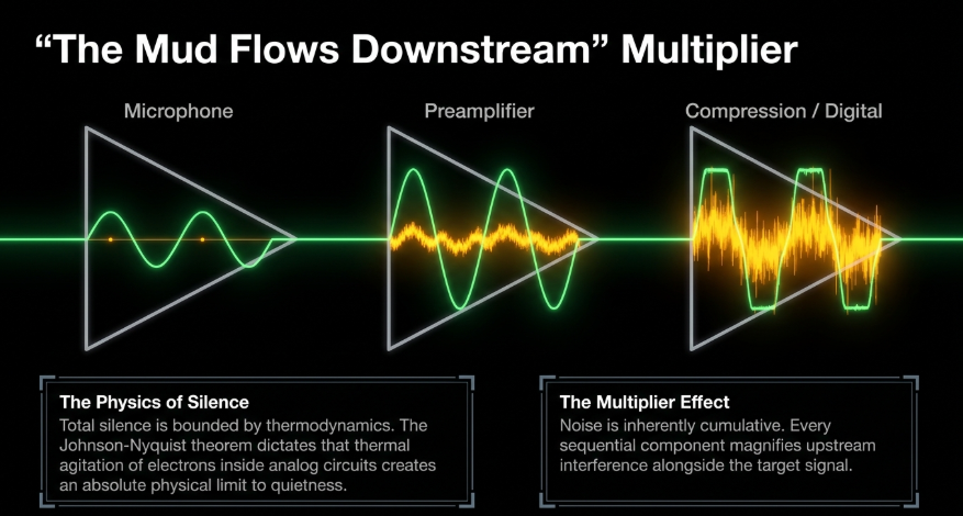
A critical, foundational principle in system design is that noise is inherently cumulative. Lewitt Audio As a signal travels sequentially from its source to its ultimate destination, every individual component inserted into the signal chain adds its own specific self-noise to the total aggregated noise floor. An acoustic environment introduces baseline room tone; a condenser microphone adds thermal hiss; a preamplifier amplifies both the room tone and the mic hiss while introducing its own circuit noise; finally, analog-to-digital converters add quantization noise. This compounding phenomenon vividly illustrates the concept that "mud flows downstream". iZotope A microscopic amount of noise introduced at the transducer stage will be exponentially magnified by subsequent amplification stages, making early-stage noise mitigation an absolute necessity. iZotope Therefore, maximizing the Signal-to-Noise Ratio (SNR)—the mathematical relationship between the desired audio signal and the unwanted background interference—at the earliest possible stage is paramount for achieving a professional outcome. Mastering The Mix
3. Gain Staging: The Architecture of Signal Integrity
The most effective, non-destructive method for managing the noise floor and maximizing the Signal-to-Noise Ratio is proper gain staging. Gain staging is the systematic, deliberate process of optimizing the signal level at every discrete stage of an audio path, ensuring that the equipment operates within its ideal mathematical parameters. It functions much like regulating the flow of water through a complex piping system; careful control is necessary to prevent either an overflow (clipping) or a low-flow situation where the system struggles to perform (low signal buried in noise).
The primary objective of gain staging is to keep the target audio signal sufficiently high above the noise floor to completely mask background hiss, while simultaneously keeping it safely below the operational ceiling to prevent catastrophic harmonic distortion. When an input signal is recorded at an excessively low level, the static noise floor of the recording medium or preamplifier represents a disproportionately large percentage of the total captured audio data. Attempting to artificially amplify this weak signal downstream during the mixing or mastering phase will uniformly amplify the inherent background hiss alongside the desired audio, resulting in a significantly degraded, noisy, and amateur-sounding track. Mastering The Mix
Conversely, capturing the signal at a high, healthy level ensures that when the track is played back, the desired audio naturally masks the self-noise of the system. In dynamic recordings, the system's noise floor may only become perceivable to the listener when the primary signal decays into absolute silence, such as the tail end of a reverberating snare drum decaying in a live acoustic room. Korneff Audio
Industry Standards and AES Guidelines
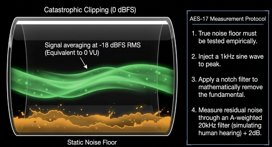
The Audio Engineering Society (AES) provides strict, peer-reviewed recommendations for metering and gain staging to preserve maximum dynamic range and prevent quantization errors. AES In modern digital audio workstations (DAWs), the industry standard practice is to align nominal average signal levels to -18 dBFS (Decibels relative to Full Scale) as displayed on a Root Mean Square (RMS) meter. This specific operational level was chosen because it effectively mirrors the traditional 0 VU (Volume Unit) mark utilized in legacy analog console metering, providing a familiar and mathematically sound translation between analog outboard gear and digital converters. Avid
Maintaining an average level between -18 dBFS and -6 dBFS ensures ample "headroom"—the vital safety margin between the average continuous signal level and the absolute digital ceiling of 0 dBFS where irrecoverable clipping occurs. Lewitt Audio Consuming this headroom by driving preamplifiers too hard introduces clipping artifacts, while failing to utilize it allows the static noise floor to encroach upon the signal's micro-dynamics. Lewitt Audio
Furthermore, standard testing methodologies for determining the true noise floor of equipment are highly regulated. The AES-17 testing protocol for measuring dynamic range, for instance, dictates evaluating the ratio of a full-scale amplitude to weighted RMS noise. Digitization Guidelines The test signal must be a 997 Hz sine wave producing exactly -60 dBFS at the equipment under test (EUT) output. Digitization Guidelines The measurement equipment then applies a standard notch filter to remove the fundamental tone, and the remaining residual noise is passed through an A-weighted filter limited to 20 kHz to simulate human hearing. Digitization Guidelines By adding 60 dB to the resulting measurement, engineers can accurately specify the total dynamic range between full output and the absolute noise floor of the amplifier or converter, providing a transparent, empirical metric of equipment quality. Texas Instruments
Gain Staging in the Digital Domain: Dithering and Quantization
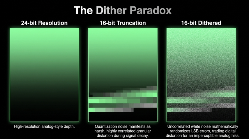
When traversing the digital domain, specific artifacts can raise the noise floor artificially. During bit-depth reduction—such as when converting a pristine 24-bit studio recording down to the 16-bit standard required for compact disc distribution or standard streaming—quantization noise is inevitably introduced. Truncating the least significant bits (LSB) of the digital word creates a highly correlated, program-dependent error that manifests as a harsh, granular distortion trailing the audio as it fades into silence. EBU/AES
To combat this mathematical degradation, European Broadcasting Union (EBU) and AES specifications dictate the application of a process known as "dithering". EBU/AES Dithering involves deliberately adding a microscopic, mathematically calculated layer of uncorrelated white noise to the signal immediately before truncation occurs. While intentionally adding noise to an audio signal seems entirely counterintuitive to the goal of lowering the noise floor, this specific low-level noise mathematically randomizes the quantization errors. EBU/AES This randomization preserves audio resolution below the theoretical limits of the bit depth, effectively trading harsh, unnatural digital distortion for a smooth, imperceptible analog-style hiss that the human brain easily ignores. EBU/AES Failing to apply dither correctly during sample rate and bit depth conversions guarantees an artificially high and unpleasant noise floor.
4. Transducer Interfacing and Hardware Amplification
A remarkably frequent cause of excessive hiss in modern recording setups is the utilization of low-output transducers paired with consumer-grade or bus-powered preamplifiers. Dynamic microphones (such as the ubiquitous Shure SM7B or Electro-Voice RE20) and passive ribbon microphones generate extremely low voltage outputs due to their physical construction. YouTube To reach nominal operational levels, these microphones require substantial preamplification, frequently necessitating upwards of 60 dB of clean gain. YouTube
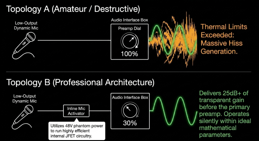
When standard preamplifiers integrated into budget audio interfaces are pushed to their maximum capacity to accommodate these gain-hungry microphones, the internal components are stressed to their thermal limits. At these extreme settings, the preamplifier's internal noise floor becomes highly audible, generating an aggressive and unacceptable hiss that dominates the recording. Mastering The Mix
Inline Microphone Preamplifiers (Mic Activators)
To mitigate this widespread issue without requiring the purchase of multi-thousand-dollar outboard studio preamplifiers, engineers deploy inline microphone preamplifiers, commonly referred to within the industry as "mic activators." These compact devices are inserted into the signal chain directly between the microphone and the primary preamplifier. Kettner Creative
Mic activators function by utilizing the standard +48V phantom power provided by the audio interface to power highly efficient internal JFET (Junction Field Effect Transistor) circuitry. Kettner Creative This circuitry provides a fixed, massive boost of ultra-clean, transparent gain before the signal ever reaches the main preamplifier. Kettner Creative Because the inline device safely blocks the +48V phantom power from reaching the delicate ribbon or dynamic elements (preventing accidental damage), it acts as a protective buffer. Kettner Creative By feeding a significantly hotter, pre-amplified signal down the XLR cable into the audio interface, the main preamplifier can be operated at a much lower, quieter setting. This architectural shift in gain staging drastically improves the total Signal-to-Noise Ratio and effectively eliminates preamplifier hiss. PedalSnake Blog
The professional audio market offers several highly engineered solutions in this category, each with specific form factors and gain topologies designed to optimize the noise floor:
The decision between utilizing a standalone unit like the Cloudlifter and a direct-attach unit like the FetHead often hinges on spatial requirements, budget, and cable management constraints within the studio, as both devices offer mathematically similar improvements to the noise floor profile. YouTube For rigorous troubleshooting purposes, deploying a mic activator immediately isolates the source of the hiss: if the hiss disappears when the activator is used and the main preamp is turned down, the original hiss was undeniably the result of the interface's thermal limits being exceeded. Kettner Creative
5. Electrical Infrastructure: AC Contamination and Ground Loops
While hiss is fundamentally a byproduct of thermal activity and gain structure, low-frequency hum and mid-frequency buzz are almost entirely symptoms of electrical infrastructure failures. A consistently high noise floor is frequently traced back to contaminated Alternating Current (AC) power lines and the manifestation of ground loops. The electrical grid is inherently noisy, acting as a massive antenna for airborne interference and a shared reservoir for the electrical pollution generated by every appliance on the circuit.
The Pathology of AC Ground Loops
An AC ground loop is one of the most persistent and frustrating challenges in professional audio engineering. It occurs when interconnected audio equipment interfaces with the building's safety ground at multiple, different physical points within the electrical system. If there is even a microscopic voltage differential between these various grounding points, electrical current will naturally flow through the path of least resistance to equalize the potential. In an audio system, this path of least resistance is frequently the copper shielding of the audio cables connecting the devices.
This unintended current flowing across the audio cable's shielding magnetically induces a 60 Hz sine wave (alongside its associated 120 Hz and 180 Hz harmonics) directly into the sensitive audio signal path. Ground loops are particularly pernicious in complex stereo guitar rigs, expansive computer-based digital audio workstations, and broadcast racks utilizing standard asymmetrical AC power distribution (consisting of a 120V hot wire, a 0V neutral wire, and a safety ground). The resulting induced noise not only significantly raises the noise floor but severely degrades high-frequency spatial cues, stereo imaging depth, and low-level transient response, masking the clarity of the audio.
Remediation via Power Conditioning and Symmetrical Isolation
To eradicate ground loop hum and radio frequency interference from the power grid, consumer-grade passive surge protectors (often colloquially mislabeled as power strips) are entirely insufficient. While power strips offer basic protection against catastrophic lightning strikes or surges, they offer zero filtration of line noise and do nothing to regulate the voltage. Sweetwater Advanced power conditioning and voltage regulation are strictly required for professional applications. Sweetwater
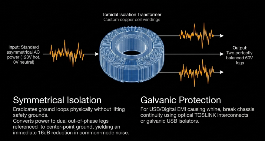
Balanced Power Transformers: The most absolute, scientifically sound solution to ground loop hum is the implementation of symmetrically balanced AC power. High-end power conditioners, such as the Furman P-2400 IT, utilize massive, custom-wound toroidal isolation transformers to completely decouple the connected audio equipment from the building's electrical grid. These transformers take the standard asymmetrical 120V power and convert it into two 60V legs of opposite polarity, referenced to a center-point ground. Because the noise riding on the hot and neutral lines is now exactly 180° out of phase with itself, the common-mode noise is phase-cancelled completely. This brilliant architectural design theoretically yields upwards of an 80 dB reduction in the noise floor without ever requiring the engineer to destructively modify or lift the ground on audio cables.
Linear Filtration Technology (LiFT): To combat differential-mode noise—the high-frequency hash introduced by modern LED dimmers, fluorescent lighting ballasts, computer power supplies, and HVAC systems—professional conditioners employ advanced low-pass filtration networks. This technology cleanly strips RFI and EMI from the AC sine wave across a massive bandwidth before the power ever enters the sensitive audio power supplies. Sweetwater
Galvanic Isolation: For direct audio pathways where balanced power is unavailable, ground loops can occasionally be broken by severing the shield connection at one end of an audio cable (a practice known as telescoping the shield) or by inserting passive ground loop isolators utilizing small audio transformers. However, passive audio transformers can sometimes saturate under heavy loads and subtly degrade signal bandwidth, making true AC-level isolation the preferred professional route. Eaton
Digital and USB Interference
In modern hybrid studios, computers and their associated peripherals represent a localized, highly concentrated nexus of EMI. Internal computer components, specifically motherboards, heavy-draw Graphic Processing Units (GPUs), and unshielded switching laptop power bricks, generate intense electromagnetic fields. When an audio interface is connected to a computer via a standard USB or HDMI cable, stray DC voltage and high-frequency digital clock noise can bleed directly through the USB bus. This interference entirely bypasses the audio interface's external shielding, injecting directly into the digital-to-analog converters (DAC) and manifesting as a chattering, modulating buzz in the studio monitors that changes pitch as the computer's CPU load fluctuates. Reddit
Remediation of this specific digital noise requires breaking the electrical continuity between the noisy computer chassis and the clean audio gear. This can be achieved using galvanic USB isolators, clamping ferrite noise suppressor chokes over the data cables, or transitioning completely to optical (TOSLINK) interconnects that transmit data via light rather than copper, offering infinite electrical resistance. Additionally, if a laptop power supply is identified as the source of a localized ground fault, utilizing a safe ground-lift device such as the Ebtech Hum X can safely resolve the loop without compromising electrical safety standards. Strymon
Cable Topologies: Balanced vs. Unbalanced Architecture
The inherent susceptibility of an audio signal to airborne EMI and RFI is largely dictated by its cabling topology and physical routing. Unbalanced lines, such as standard RCA cables used in hi-fi stereos or TS (Tip-Sleeve) cables used for electric guitars, utilize a single internal conductor for the audio signal and rely on the outer metallic shield to act as the electrical ground. Reddit Any EMI that successfully penetrates this outer shield is immediately mixed directly into the audio signal and amplified downstream, permanently raising the noise floor. Reddit
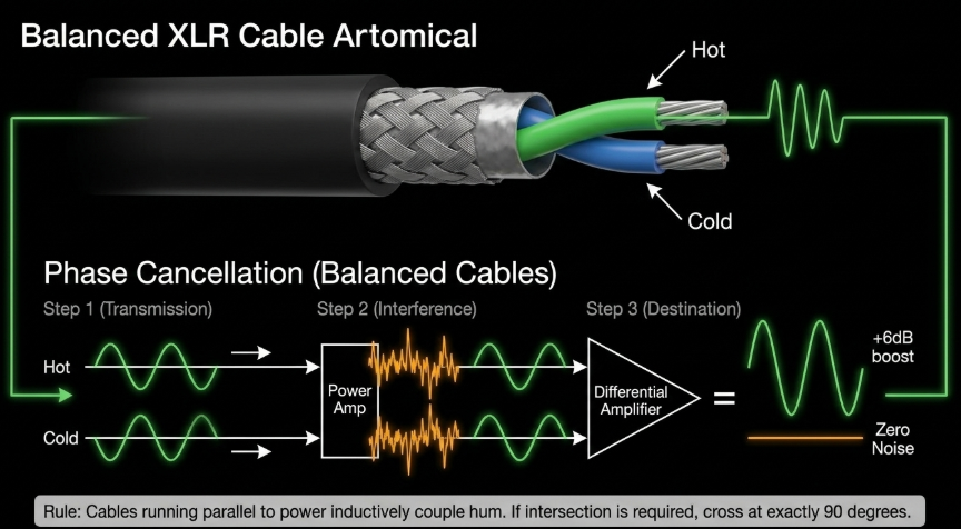
Conversely, professional audio relies almost exclusively on balanced cabling systems, utilizing XLR or TRS (Tip-Ring-Sleeve) connectors. A balanced cable features two identical internal signal conductors (typically designated as hot and cold) surrounded by a separate, dedicated ground shield. Totem Acoustic The sending device transmits the audio signal down both conductors simultaneously, but deliberately inverts the phase of the cold conductor by exactly 180°. Reddit As the cable runs through complex EMI fields—such as behind a rack of power amplifiers—both conductors pick up the exact same environmental noise in phase with one another. At the receiving end, a differential amplifier flips the cold signal back to its original phase. Reddit This ingenious mechanism realigns the audio signal constructively (resulting in a 3 dB boost in signal strength) while simultaneously throwing the accumulated environmental noise perfectly out of phase, causing total phase cancellation of the interference. Reddit Replacing long unbalanced runs with balanced lines is a primary, mandatory vector for lowering the systemic noise floor in any professional installation.
Furthermore, physical cable management plays a crucial role. Audio cables running parallel to power cables will inductively couple, transferring hum directly into the audio path. iZotope Industry best practices dictate keeping power cables and audio interconnects strictly separated; if they must intersect due to spatial constraints, they must cross at exactly a 90-degree angle to minimize the inductive footprint. Totem Acoustic
6. Signal Chain Diagnostics: Systematic Troubleshooting Methodologies
When confronted with an abnormally high noise floor, a mysterious hum, or the sudden disappearance of a signal, amateur operators often resort to randomly unplugging cables or blindly altering software parameters. This chaotic approach typically compounds the error and wastes valuable studio time. Sound On Sound Professional engineers instead rely on rigorous, deductive logical frameworks to isolate and identify faults within complex signal chains.
The Half-Splitting Algorithm
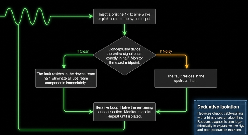
Adapted directly from complex electrical systems engineering, the half-splitting method is a highly efficient binary search algorithm applied to audio troubleshooting. Ques10 Rather than checking every individual component sequentially from the sound source to the final output, the engineer conceptually divides the entire signal chain exactly in half. Ques10 By probing, soloing, or monitoring the midpoint of the system, the engineer determines whether the fault (e.g., severe hiss or a missing signal) is present at that exact stage. Ques10
If the signal at the midpoint is clean and noise-free, the entire first half of the signal chain is definitively eliminated as the source of the problem, meaning the fault must reside somewhere in the downstream half. Ques10 The remaining suspect section is then halved again, and the monitoring process repeats. Ques10 In complex live sound rigs or expansive post-production matrices involving dozens of outboard hardware units and complex digital routing, half-splitting reduces diagnostic time logarithmically compared to linear, component-by-component checking. Ques10
Signal Injection and Tracing
As a corollary to the half-splitting method, signal tracing involves injecting a known, pristine test signal—typically a 1 kHz sine wave or broadband pink noise generated by an oscillator—at the system's input. The engineer then tracks the signal's potential degradation through each subsequent amplification stage using an oscilloscope, a fault tracer, or a console's metering bridge. Scribd
Alternatively, the engineer can inject the test signal at various midpoints, moving progressively backward toward the source until the signal fails to pass cleanly or exhibits a massive increase in the noise floor. All About Circuits This method is exceptionally useful for identifying specific hardware components where internal impedance mismatches, degraded capacitors, or blown operational amplifiers are artificially raising the noise floor. Robs Radioactive
When dealing with interconnected digital pedalboards or complex synth rigs, testing individual units one by one while utilizing a highly isolated, multi-output power supply (such as the Strymon Zuma or Ojai) helps ensure that ground loops and digital clock noise are systematically ruled out. Strymon If a specific pedal generates noise when connected to a truly isolated power supply, the fault is isolated to the pedal's internal circuitry rather than the external power grid. Strymon
7. Acoustic Environmental Control: Managing Ambient Noise
Before a system's electrical self-noise can be properly addressed, the physical space in which the recording takes place must be rigorously controlled. A highly sensitive condenser microphone does not possess the psychoacoustic ability to differentiate between thermal amplifier hiss, the drone of a central HVAC system, or the distant rumble of traffic; all of these elements constitute the total ambient noise floor. Whisper Room
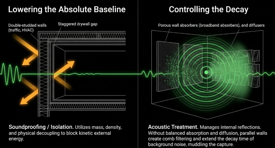
There is a critical, frequently misunderstood distinction in acoustics between soundproofing (isolation) and acoustic treatment. Soundproofing utilizes immense physical mass, density, and physical decoupling to prevent external kinetic energy from penetrating the recording space. Fluid Audio This is often achieved through "room-within-a-room" construction methodologies, utilizing floated floors, double-studded walls with mass-loaded vinyl, and staggered drywall to break physical vibrations. Fluid Audio Soundproofing directly lowers the absolute baseline decibel level of the room's noise floor, effectively blocking outside interference. Whisper Room
Acoustic treatment, conversely, addresses the behavior of sound waves inside the room once the sound has been generated. Hard, parallel surfaces like drywall and glass cause sound waves to reflect continuously, creating comb filtering, flutter echoes, and problematic low-frequency room modes. Fluid Audio These reflections muddy the captured audio and effectively extend the decay time of any background noise, making the room sound small and highly reverberant. Fluid Audio By strategically deploying broadband absorbers made of high-density mineral wool, acoustic foam, and dedicated corner bass traps, engineers can absorb stray reflections, preventing the "boxy" coloration of a room and bringing the ambient noise floor to a controlled, rapid decay. Fluid Audio
However, over-treating a room with inexpensive, thin foam exclusively absorbs high frequencies, resulting in an unnaturally "dead" high-end while leaving low-end rumble completely untreated. It is vital to maintain a balanced acoustic profile using diffusers alongside absorbers, ensuring the room sounds natural while maintaining a low ambient noise floor. Reddit Modular isolation booths provide an immediate, highly effective combination of both isolation and treatment for vocal recordings, circumventing the need for extensive architectural modifications.
8. Digital Signal Processing: Advanced Noise Remediation
Despite the implementation of flawless gain staging, pure balanced power, and pristine acoustic environments, certain realities of audio production remain unavoidable. Legacy archival recordings, uncontrollable location sound for film, and field dialogue invariably contain residual noise. Swell AI When all preventative physical and electrical measures have been completely exhausted, the audio post-production phase relies on advanced Digital Signal Processing (DSP) to lower the noise floor retroactively. iZotope The application of DSP must be exceedingly precise, as excessive or clumsy processing introduces destructive digital artifacts that are often more fatiguing and distracting to the listener than the original hiss.
Traditional Dynamics: Expanders and Noise Gates
The foundational tools for managing the noise floor in a mix environment are dynamic processors, specifically noise gates and downward expanders. Audacity
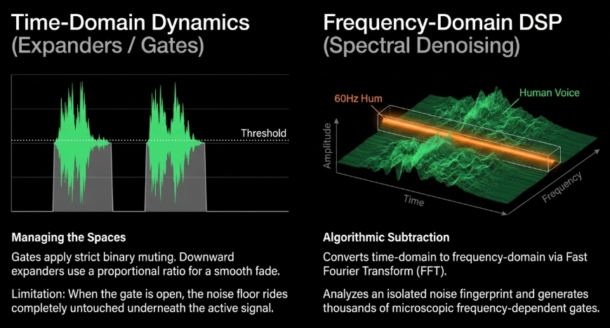
A noise gate acts as a strict, binary switch. When the amplitude of the audio signal falls below a specific, user-defined volume threshold, the gate "closes," applying near-infinite attenuation to mute the channel completely. Gates are highly effective on sharp, percussive material, such as shutting off microphone bleed from a high-hat into a snare drum microphone in the milliseconds between tom hits. Unison Audio However, on sustained, complex signals like human vocals or bowed strings, strict noise gates can sound incredibly jarring, abruptly cutting off the natural decay of room reverberation or the subtle breaths of a vocalist. Lewitt Audio
Downward expanders operate on a much softer, more musical mathematical curve, acting effectively as a "reverse compressor". Lewitt Audio Rather than instantly muting the signal below the threshold, an expander reduces the gain by a specific, proportional ratio (e.g., 1:2, meaning for every 1 dB the signal falls below the threshold, it is actively attenuated by 2 dB). Sound On Sound This creates a smooth, transparent fade into the noise floor, retaining the natural envelope of acoustic instruments and dialogue while gently pushing the background hiss out of the listener's perception. Lewitt Audio
However, both gates and expanders share a fundamental limitation: they only manage the spaces between words or notes. They do absolutely nothing to remove the noise floor during the active signal; when the gate opens, the hiss rides perfectly underneath the audio, completely unattenuated. Sound On Sound
The Revolution of Spectral Denoising
To surgically extract broadband noise from within the active audio signal without simply muting the channel, the industry relies on the profound mathematical power of spectral editing. Spectral denoisers operate by converting standard time-domain audio data (which represents amplitude over time) into the frequency domain using highly complex Fast Fourier Transform (FFT) algorithms. Reddit The FFT divides the continuous audio stream into thousands of tiny, distinct frequency bins, allowing the software to analyze the exact amplitude and phase of every individual frequency simultaneously, independent of time. Reddit
The spectral denoising workflow, heavily popularized by advanced software suites like iZotope RX, requires a highly structured, almost forensic order of operations iZotope:
Noise Fingerprinting: The audio engineer highlights a small section of "pure" noise (such as isolated room tone or blank tape hiss) containing no dialogue or musical content. iZotope The software analyzes and "learns" this specific FFT profile, precisely mapping the frequency distribution, amplitude, and phase of the unwanted noise floor across the entire spectrum. solidskillsy
Threshold Mapping: Utilizing the learned profile, the algorithm dynamically creates thousands of microscopic, frequency-dependent noise gates. Reddit
Algorithmic Subtraction: As the audio file plays, the processor actively subtracts the learned noise profile from the entire file. Because the audio is separated into independent frequency bands, a constant 60 Hz hum or broadband tape hiss can be mathematically erased even while a vocalist is singing directly over it, without dulling or heavily filtering the high frequencies of the vocal itself.
Comparative Analysis of Industry-Standard Restoration Suites
The modern landscape of audio repair is dominated by a few pinnacle software and hardware tools, each utilizing profoundly different technological philosophies ranging from traditional FFT mathematics to cutting-edge neural networks.
The choice between these specific paradigms depends entirely on the nature of the noise floor. A static, unmoving cassette tape hiss or a steady air conditioning drone is perfectly suited to the algorithmic subtraction of iZotope's Spectral De-noise. Reddit Conversely, an unpredictable, constantly shifting background noise floor—such as a bustling coffee shop, rustling clothing, or erratic wind noise—will instantly foil standard FFT profiling and demands the machine learning, pattern-recognition power of tools like Dialogue Isolate or Waves Clarity Vx. Reddit
The Strict Order of Operations in Audio Repair
When attempting to eliminate a complex, high noise floor alongside other audio defects, the exact sequence in which DSP is applied is critical to avoid cascading artifacts. iZotope Applying creative equalization or dynamic compression before performing noise reduction is a severe structural error.
Compression reduces the dynamic range of a signal; by turning down the loudest peaks and applying makeup gain, the compressor draws the noise floor aggressively upward. This shrinks the Signal-to-Noise Ratio and makes the noise infinitely harder for the FFT algorithm to distinguish from the primary transient signal. Reddit Equalization, particularly high-frequency shelving boosts designed to add "air" to a vocal, will merely exaggerate the broadband hiss, baking it into the signal. Mastering The Mix
The definitive industry order of operations dictates that audio repair—specifically spectral denoising, de-humming, and de-clicking—must be performed fully offline on the raw audio before any standard mixing processors (EQ, compression, limiting) are engaged. iZotope Once the raw audio has been algorithmically sanitized and the static noise floor mathematically lowered, a subtle multi-band expander can be placed early in the DAW insert chain to transparently manage any residual low-level room tone during pauses, allowing subsequent compression to operate on a beautifully clean, silent background. Sound On Sound
9. Conclusion
The identification and elimination of a high noise floor is rarely, if ever, solved by a singular intervention; it is a holistic, exacting discipline that demands absolute control over the physical, electrical, and digital domains. Background hiss, low-frequency hum, and erratic digital hash represent distinct, measurable physical phenomena—originating from the thermal chaos of analog circuitry, the powerful electromagnetic induction of poorly planned ground loops, and the granular mathematical reality of digital quantization.
To engineer an environment of absolute sonic purity, practitioners must address the signal chain sequentially and logically, honoring the principle that noise builds cumulatively as it flows downstream. It begins in the physical realm with architectural isolation and strategic acoustic treatment to suppress the environmental room tone. Fluid Audio It requires meticulous power management, utilizing massive balanced isolation transformers to physically break ground loops and strip high-frequency EMI from the AC lines before power ever enters the recording equipment. It necessitates the deployment of robust gain staging protocols—strictly targeting -18 dBFS for nominal levels—and the calculated use of inline mic activators to maximize the Signal-to-Noise Ratio at the delicate transducer level. Mastering The Mix
Only when the analog and structural architectures are fully optimized should the engineer pivot to digital signal processing to clean up residual artifacts. While modern neural networks and FFT-based spectral denoisers possess near-miraculous capabilities for retroactive repair, they remain inherently destructive processes that alter the phase and frequency response of the original source material. The ultimate benchmark of professional audio engineering is not the mastery of software to erase a high noise floor, but the mastery of physics, electronics, and acoustics to ensure that the noise floor never breaches the threshold of human perception in the first place.