Introduction to Acoustic and Thermodynamic Synchronization
The design and construction of critical listening environments—particularly high-density recording studios, mastering suites, and broadcast facilities—represent one of the most mathematically rigorous and physically uncompromising disciplines within architectural engineering.
Unlike conventional commercial office spaces, which are engineered to balance basic human thermal comfort with economic spatial efficiency, professional recording facilities demand absolute acoustic transparency and precise thermodynamic regulation. When the architectural mandate involves retrofitting a standard commercial office space to meet the stringent Noise Criterion 25 (NC-25) rating while simultaneously cooling high-density electronic equipment, engineers are immediately confronted with a highly complex, multi-variable optimization problem. Hitachi Aircon
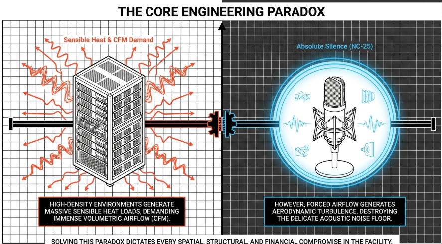
The core conflict in such retrofits arises from the inverse relationship between acoustic isolation and spatial conservation, coupled with the direct fluid dynamic relationship between thermodynamic heat load and air velocity. High-density audio and computing equipment generates massive sensible heat loads, necessitating high volumes of conditioned air, measured in Cubic Feet per Minute (CFM). However, forcing high volumes of air through standard commercial office ductwork elevates the air velocity, measured in Feet per Minute (FPM), which subsequently generates severe aerodynamic turbulence and broad-spectrum acoustic noise. To maintain an NC-25 acoustic rating, air velocity must be strictly minimized, thereby requiring exponentially larger ductwork and extensive labyrinthine baffle systems.
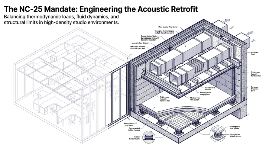
Simultaneously, achieving an NC-25 background noise level by blocking external environmental noise requires massive, decoupled architectural assemblies—often referred to as mass-spring-mass (MSM) systems or room-within-a-room construction. These dense structures introduce dead loads that frequently exceed the structural capacity of standard commercial floors, while their physical depth consumes immense cubic volume, drastically reducing the usable square footage and ceiling height of the leased space. This report provides an exhaustive mathematical analysis of the formulas linking heat load to required air velocity, and critically examines the exact architectural, structural, spatial, and legal compromises that must be enacted to successfully retrofit a commercial office into a high-density, NC-25 recording facility.
Thermodynamic Principles and High-Density Heat Loads
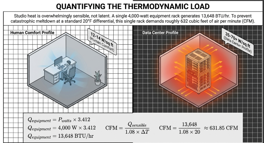
The foundational step in designing the mechanical infrastructure for a high-density recording studio is quantifying the thermodynamic load. High-density studio environments are unique because their heat generation is overwhelmingly sensible (dry heat radiating from analog consoles, outboard gear, power amplifiers, and computer servers) rather than latent (moisture-based heat from human respiration, plants, and ambient humidity). CEDengineering
Quantifying the High-Density Sensible Heat Load
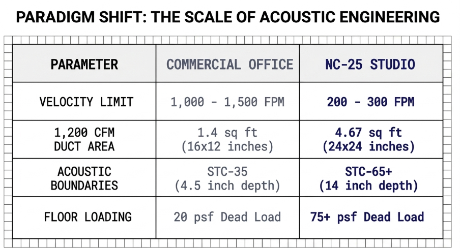
Standard commercial office spaces are designed to handle relatively modest heat loads of approximately 12 to 14 watts per square foot. This corresponds to roughly one ton of comfort cooling capacity (defined as 12,000 British Thermal Units per hour, or BTU/hr) for every 250 to 300 square feet of floor space. In stark contrast, high-density recording environments housing racks of analog processing gear, digital converters, and servers mirror the thermal profiles of data centers. These environments easily reach load densities of 35 to 70 watts per square foot, and in ultra-high-density equipment closets or machine rooms, loads can rapidly scale up to 200 to 300 watts per square foot. CEDengineering
To calculate the total sensible heat load ($Q_{sensible}$), the maximum power consumption of all electrical equipment must be converted into BTU/hr. Since one hundred percent of the electrical input power consumed by computing and audio equipment is ultimately dissipated into the room as heat, the conversion is a direct thermodynamic translation. The fundamental relationship is defined as:
The Sensible Heat Airflow Formula
Once the total sensible heat load ($Q_{sensible}$) is calculated by aggregating the equipment load, the high-intensity studio lighting load, and the thermal envelope transmission load, the mechanical engineer must determine the volumetric flow rate of air required to remove this heat and prevent equipment failure. The fundamental sensible heat equation for air is universally expressed in the HVAC industry as:
Latent Heat, Enthalpy, and Dehumidification Conflicts
While sensible heat overwhelmingly dominates the equipment footprint, the presence of human occupants—producers, engineers, and musicians—introduces a latent heat load primarily through respiration and perspiration. Latent heat removal depends on the change in the humidity ratio of the air, representing the physical condensation of moisture on the evaporator coil. Energy Vanguard The latent heat formula is defined as: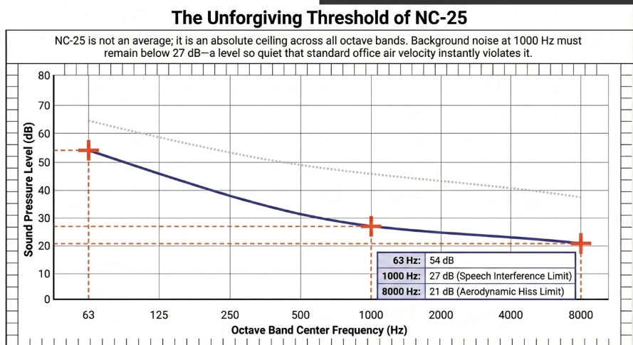
Acoustic Baselines: The Noise Criterion 25 (NC-25) Threshold
The defining characteristic of a professional recording studio is its vanishingly low noise floor, which is typically defined by the Noise Criterion (NC) rating system. Titus HVAC Developed in 1957 by Leo Beranek, the NC rating is a single-number metric derived from measuring steady-state background noise—usually generated by HVAC systems and mechanical equipment—across the human hearing spectrum. ASHRAE NWA
To calculate an NC rating, an acoustician uses a calibrated sound-level meter and frequency analyzer to capture octave-band sound pressure levels (SPL) from 63 Hz to 8,000 Hz. These measured levels are plotted against a set of standard NC curves. The highest curve that the measured spectrum touches or exceeds determines the official NC rating for the room. Commercial Acoustics
Defining the NC-25 Profile
To achieve an NC-25 rating—the widely accepted baseline for high-quality recording studios, broadcast facilities, and critical listening environments—the background noise within the room must not exceed the acoustic thresholds defined by the NC-25 curve at any octave band. The precise sound pressure level maximums for the NC-25 octave bands are highly restrictive, particularly in the mid-to-high frequencies where the human ear is most sensitive to the "hiss" generated by turbulent airflow, and the speech interference level (SIL) range between 500 Hz and 2000 Hz. Titus HVAC
As demonstrated by the structured data above, achieving an NC-25 rating requires the 1000 Hz band to remain at or below 27 dB, and the 8000 Hz band to drop to a virtually imperceptible 21 dB. Crystal Instruments By comparison, a standard commercial office space is typically designed to hit NC-35 or NC-40. Commercial Acoustics An office at NC-40 allows for 64 dB at 63 Hz and 37 dB at 8000 Hz. Crystal Instruments This higher baseline in offices actually serves a functional purpose: the mechanical background noise acts as a sound-masking agent, providing speech privacy between cubicles. Titus HVAC In a recording studio, however, any background noise masks the delicate nuances of recorded instruments and raises the noise floor of sensitive condenser microphones. Commercial Acoustics
It is also important to note that single-number metrics like dB-A (A-weighting) are insufficient for studio design. dB-A applies a weighting filter that drastically reduces the measured impact of low-frequency sound to approximate the threshold of human hearing (the Fletcher-Munson contours). ASHRAE NWA However, low-frequency rumble from HVAC systems is notoriously difficult to trap acoustically and can ruin low-end monitoring accuracy in a studio. ASHRAE NWA Therefore, full octave-band analysis using NC or Room Criteria (RC) curves—which evaluate both speech interference and low-frequency rumble—is strictly required. Titus HVAC
Fluid Dynamics: Coupling Heat Load to Air Velocity
The primary antagonist to the NC-25 rating is HVAC-induced aerodynamic noise. When air travels through ductwork, friction against the duct walls and turbulence at elbows, transition fittings, dampers, and diffusers generates broad-spectrum acoustic energy. ASHRAE The intensity of this aerodynamically generated sound is proportional to the velocity of the air. As air speed increases, the flow transitions from smooth laminar flow to chaotic turbulent flow, triggering severe noise radiation into the duct plenum, through the duct walls, and out into the occupied space.
The Continuity Equation and Velocity Pressure
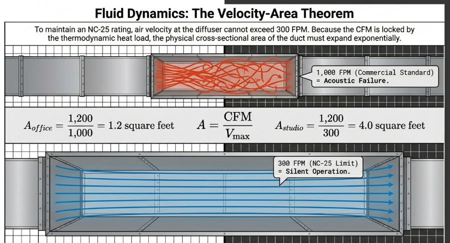
The standard relationship between volumetric airflow (CFM), air velocity (FPM), and the cross-sectional area of the duct ($A$, measured in square feet) is defined by the continuity equation for incompressible flow:
$$V=\frac{CFM}{A}$$
Alternatively, to find the required duct area for a targeted velocity:
$$A=\frac{CFM}{V}$$
Furthermore, the velocity of the air relates directly to the dynamic velocity pressure ($P_{v}$, measured in inches of water column) via the following equation:
$$V=4,005\times\sqrt{P_{v}}$$
In this formula, 4,005 is a standard constant that converts inches of water velocity pressure into feet per minute for standard air. For example, a velocity pressure of 0.20 inches of water yields an air velocity of approximately 1,790 FPM. Belimo High velocities not only create acoustic noise but exponentially increase friction loss (measured in inches of water column per 100 feet). While standard office duct design utilizes a friction loss rate of 0.1" w.c./100 ft, complex studio systems with long runs and many acoustic baffles often require a more conservative 0.08" w.c./100 ft to prevent fan motor overload and excessive static pressure. Portlandia Electric
Velocity Constraints for NC-25
In a standard commercial office setting, HVAC engineers typically design main supply ducts to operate at velocities between 1,000 and 1,500 FPM, and branch ducts between 600 and 900 FPM. Portlandia Electric These velocities perfectly mask the sound of office chatter without causing physical discomfort.
However, in a recording studio targeting an NC-25 rating, these commercial velocities are entirely unacceptable. According to ASHRAE technical specifications, Carrier guidelines, and acoustical engineering standards, to meet an NC-25 criterion, the air velocity at the supply diffusers and branch ducts must not exceed 200 to 300 FPM. Furthermore, the air velocity in the main ductwork upstream of the acoustic baffle boxes must be strictly restricted to 400 to 600 FPM. HVAC-eng Exceeding 300 FPM at the diffuser virtually guarantees that the aerodynamic "hiss" Soundproof Your Studio and turbulence will exceed the 27 dB limit at 1000 Hz, instantly failing the NC-25 requirement.
The Integrated Heat-Velocity-Area Theorem
The core engineering conflict is illuminated when the thermodynamic formula is merged with the fluid dynamic continuity equation. By substituting the CFM formula into the area formula, we derive the exact relationship between the sensible heat load of the studio, the strict velocity limits of the NC-25 rating, and the required physical size of the ductwork: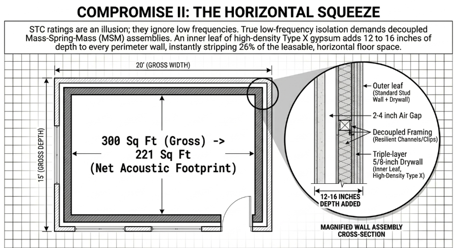
This unified equation mathematically dictates the architectural compromises of the space. To demonstrate the severity of this compromise, consider a studio control room requiring 1,200 CFM to cool its high-density processing racks. In a standard office (allowing 1,000 FPM):
Duct Size Comparisons: Commercial vs. Acoustic
The necessity for expanded duct cross-sections introduces massive spatial requirements. Rectangular ducts must also account for equivalent diameter fluid dynamics, as the corners of rectangular ducts introduce boundary layer friction that reduces efficiency. The equivalent diameter ($D_{e}$) is calculated as:
Architectural Compromise I: Volumetric Depletion and the Baffle Box Penalty
When an organization leases a standard commercial office space to retrofit into a studio, the quoted square footage and ceiling height represent gross boundaries. The creation of an NC-25 acoustic shell combined with oversized low-velocity HVAC infrastructure imposes severe penalties on the physical geometry of the usable space. A primary cause of this volumetric depletion is the implementation of acoustic baffle boxes.
The Mechanics of HVAC Silencers
While oversizing the ductwork reduces aerodynamic hiss at the diffuser, it does nothing to prevent mechanical noise from the distant fan motor from traveling down the duct, nor does it stop environmental noise from entering the studio through the hollow duct conduit. To prevent noise flanking, the system requires the installation of extensive HVAC silencers, commonly known as baffle boxes or plenum silencers.
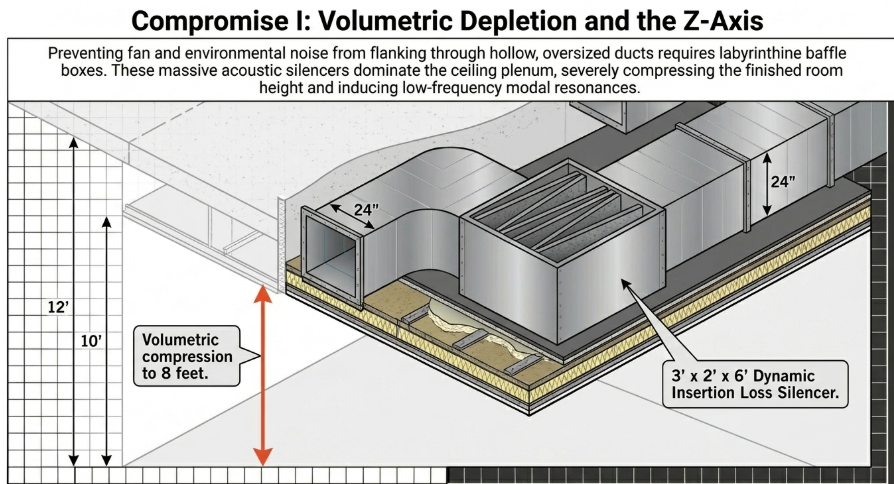
A baffle box is a massive, custom-built structural enclosure designed to force incoming air through a labyrinthine "zigzag" pathway. The interior of the box features staggered baffle walls lined with highly absorptive material, such as rigid acoustic fiberglass duct board or recycled cotton liner. As sound waves travel down the duct, they cannot bend around corners as easily as fluid air; instead, they strike the absorptive baffles. The acoustic energy causes the fibers in the liner to vibrate, converting the sound waves into microscopic amounts of heat, which is then carried away by the airflow. Soundproof Your Studio This process is quantified by Dynamic Insertion Loss (DIL), measured across octave bands. Ruskin
The Z-Axis Spatial Penalty
To handle 1,000 CFM at velocities below 300 FPM without causing severe static pressure drops, these baffle boxes must maintain internal cross-sections that are massive. Because the internal baffles block portions of the airflow path, the external dimensions of the box must be significantly larger than the connecting ductwork to maintain the overall cross-sectional area. A baffle box designed for an NC-25 studio frequently reaches external dimensions of 3 feet in width, 2 feet in height, and 5 to 6 feet in length. Furthermore, the exterior of the box must be built from dense materials—typically 3/4-inch plywood encased in multiple layers of 5/8-inch drywall—to prevent noise from breaking out of the box before it reaches the room. Price Industries
Standard commercial office spaces are typically constructed with structural slab-to-slab heights of 11 to 12 feet, with suspended acoustic drop ceilings establishing a finished room height of 9 to 10 feet. Unique HVAC Accommodating a network of 24-inch ductwork and multiple 6-foot-long acoustic baffle boxes above the isolated studio ceiling forces the architect to drastically drop the inner ceiling. Studio Design Forum In many commercial retrofits, the necessity to conceal this NC-25 compliant HVAC infrastructure forces the final finished ceiling height down to a claustrophobic 8 feet. Soundproof Your Studio This severe Z-axis compression compromises the volumetric acoustics of the room, creating uncomfortable low-frequency modal resonances (room modes) that Soundproof Your Studio require the installation of even more internal acoustic treatment, further shrinking the room.
Architectural Compromise II: Mass-Spring-Mass Systems and Horizontal Spatial Loss
Achieving an NC-25 rating requires isolating the studio not only from internal HVAC noise, but from exterior traffic noise, adjacent office chatter, and structural vibrations. The physics of sound isolation dictate that standard commercial partition walls—typically a single row of metal studs clad in 1/2-inch drywall—cannot prevent the transmission of low-frequency acoustic energy.
The Illusion of STC Ratings
Standard commercial wall assemblies are evaluated using the Sound Transmission Class (STC) rating. However, STC was developed in the 1960s specifically to measure the attenuation of human speech in offices and residential buildings. Soundproof Your Studio The STC calculation exclusively measures frequencies between 125 Hz and 4,000 Hz. Soundproof Your Studio Because recording studios generate and are affected by frequencies well below 125 Hz (such as kick drums, bass guitars, or the rumble of a passing truck), relying solely on STC ratings is highly misleading. Soundproof Your Studio Two walls with the same STC rating can perform drastically differently at 60 Hz.
To effectively isolate low frequencies, architects must utilize the principles of the Mass Law and decouple the structures entirely. This requires a "room-within-a-room" construction, technically known as a fully decoupled two-leaf mass-spring-mass (MSM) isolation system.
Decoupling and the Depletion of Usable Square Footage
In an MSM paradigm, the existing office walls form the outer leaf (Mass 1). A deep airspace is established (the Spring), and an entirely new, structurally independent set of framed walls is constructed inside the room to form the inner leaf (Mass 2). To achieve the necessary low-frequency isolation required for an NC-25 interior, the inner walls must possess extreme mass. Standard acoustic construction dictates utilizing two to four layers of 5/8-inch thick, high-density Type X gypsum board, often sandwiched with viscoelastic damping compounds. Soundproof Your Studio
The architectural compromise is the devastating loss of horizontal floor space. A standard interior office wall is typically 4.5 to 6 inches thick. Plan7Architect A decoupled studio partition requires the existing wall, an air gap of at least 2 to 4 inches to lower the resonance frequency of the MSM system, a separate framing system (3.5 to 5.5 inches for wood or heavy-gauge steel studs), and multiple layers of 5/8-inch drywall (1.25 to 2.5 inches thick). The total depth of a single perimeter wall assembly easily reaches 12 to 16 inches. Plan7Architect
If a commercial office room measures 20 by 15 feet (300 square feet), stripping 14 inches from every perimeter wall reduces the internal dimensions to roughly 17.6 by 12.6 feet (221 square feet). This represents an immediate 26% loss of usable square footage solely dedicated to horizontal acoustic isolation boundaries. When calculating the Time-Space Percentage for lease valuations or tax deductions, this lost footage significantly alters the financial viability of the space, as the tenant pays for the gross commercial square footage but can only utilize the drastically reduced net acoustic footprint. Tom Copeland
The Weight of Mass Integration
The mass required for these walls is substantial. Drywall weights vary strictly by thickness and composition:
An inner acoustic leaf utilizing three layers of standard 5/8-inch drywall introduces 6.6 pounds of dead weight per square foot of wall surface. Soundproofing Company A 10-foot-tall wall spanning 20 linear feet generates nearly 1,320 pounds of mass resting entirely on the inner floor structure. This sheer weight introduces the next critical architectural compromise: structural floor loading.
Architectural Compromise III: Structural Load Crisis and Floating Floors
Commercial office buildings are strictly engineered to handle specific weight limits, categorized into live loads (transient weight from people, desks, and temporary equipment) and dead loads (the permanent weight of the building's structure and partition walls). Reddit
The Incompatibility of Commercial Floor Ratings
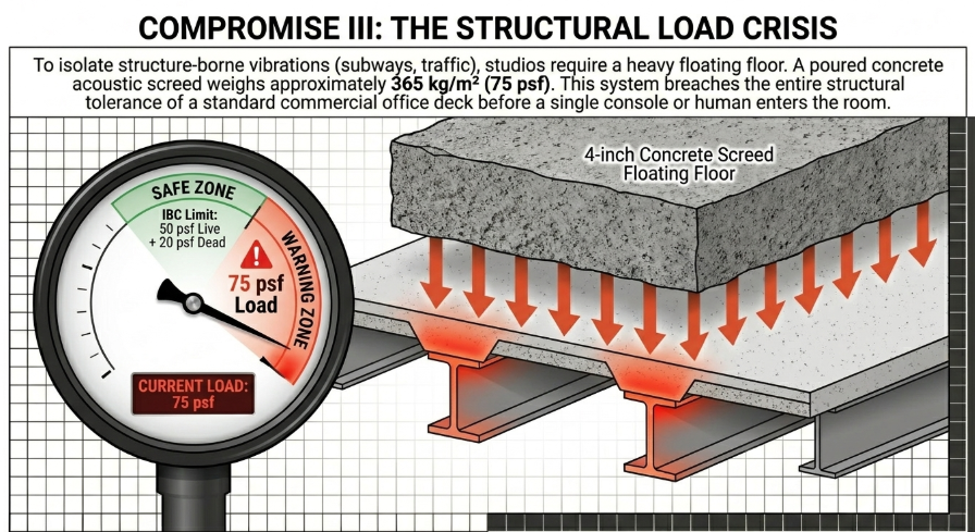
According to the International Building Code (IBC) and standard engineering practices (such as BS8110), typical commercial office floors, lobbies, and corridors above the first floor are designed to support a uniformly distributed live load of exactly 50 pounds per square foot (psf). MiTek Additionally, a superimposed partition dead load of roughly 15 to 20 psf is factored into the design to account for standard cubicles and drywall partitions. MiTek These structural limits are fundamentally incompatible with the extreme mass required for high-performance acoustic isolation.
To achieve an NC-25 rating, particularly to isolate against low-frequency structure-borne vibrations (such as subway rumbles, heavy truck traffic, or adjacent building machinery), acoustic designers specify the installation of a floating floor. A true acoustic floating floor relies on the principle of mechanical decoupling, utilizing a heavy, rigid mass "floating" atop resilient elastomeric isolators or heavy-duty steel springs. J.A. Brown Company
The Concrete Screed vs. Structural Code
The most effective floating floors—and the gold standard for isolating high-density studios—utilize a wet-poured concrete screed. A typical specification involves a 2.5-inch to 4-inch reinforced concrete slab poured over a 1-inch to 2-inch layer of high-density mineral wool or specialized rubber isolation mats (e.g., neoprene pads or Regufoam). ROCKWOOL
The physical weight of this assembly is staggering. A standard concrete floating floor system yields a total floor area dead weight of approximately 365 kilograms per square meter, which translates to nearly 75 pounds per square foot (psf). ROCKWOOL
When a 75 psf floating floor is proposed for a commercial office deck rated for a maximum total live load of 50 psf, a structural crisis emerges. International Building Code 2003 The concrete floating floor alone consumes and exceeds the entire structural tolerance of the building deck before a single piece of heavy studio equipment, mixing console, or human occupant is introduced into the room. Firgelli Automations Furthermore, the massive weight of the decoupled inner walls (the triple layers of 5/8-inch drywall) must be built on top of the floating floor to maintain the integrity of the acoustic envelope. Soundproof Your Studio This adds hundreds of pounds of point-load force to the perimeter of the floating slab, concentrating immense shear stress on the structural joists of the office building.
The Lightweight Compromise
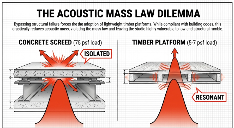
To bypass a catastrophic structural failure, architects and structural engineers must enact severe compromises. If the commercial lease or building owner prohibits structural steel reinforcement of the existing floor joists, the dense concrete floating floor must be abandoned. Steller Floors The necessary compromise is the adoption of a lightweight timber platform floor. ROCKWOOL
A lightweight floating floor consists of two layers of engineered board material (such as 18mm tongue-and-groove chipboard and 19mm plank plasterboard) resting on a resilient fiberglass or rubber layer. ROCKWOOL This assembly brings the floor area weight down to a much safer 25 to 35 kilograms per square meter (approx. 5 to 7 psf). ROCKWOOL However, according to the acoustic mass law, this drastic reduction in mass heavily compromises the floor's ability to attenuate low-frequency noise. A lightweight floor is prone to resonance and drum-like reverberation, making the NC-25 goal significantly harder to achieve and leaving the studio highly vulnerable to low-end structural vibrations transmitted from the surrounding commercial building. JCAA
Architectural Compromise IV: Egress, ADA Compliance, and the Threshold Dilemma
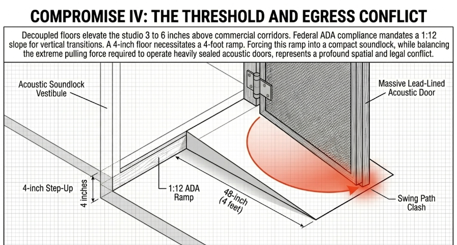
The decision to implement any form of floating floor, whether a heavy concrete screed or a lightweight timber platform, inherently alters the elevation of the studio floor relative to the existing commercial corridors. Hardwood Flooring forum A typical floating floor system raises the interior elevation by 3 to 6 inches above the structural deck. Soundproof Your Studio This seemingly minor elevation change triggers a complex cascade of compliance issues regarding building egress and the Americans with Disabilities Act (ADA). SafePath Products
Vertical Transitions and the ADA Ramp Penalty
In commercial office retrofits, federal and local accessibility codes mandate that a continuous and unobstructed way of egress travel be maintained. eCFR When an architectural acoustician specifies a 4-inch floating floor, a vertical threshold is created at the entry door of the studio. According to ADA Standards for floor and ground surfaces, vertical floor transitions cannot simply be left as steps. Raised thresholds and floor level changes at accessible doorways must be beveled with a slope no greater than 1:2 (a 50% grade) for very short vertical rises, but for changes exceeding 0.5 inches, a compliant wheelchair ramp must be installed. A compliant ADA ramp requires a slope of 1:12, meaning that for every 1 inch of vertical rise, the ramp must extend 12 inches horizontally. Access-Board.gov
If the studio floating floor is 4 inches high, an ADA-compliant ramp measuring exactly 48 inches (4 feet) in length must be integrated either into the external commercial corridor or internally within the studio. SafePath Products In tight commercial leases, external corridors are common areas that generally cannot be modified, forcing the 4-foot ramp to intrude into the meticulously planned studio interior.
The Acoustic Door and Soundlock Conflict
This ramp introduction creates a severe acoustic liability. The entry sequence into an NC-25 studio typically involves an acoustic airlock or soundlock vestibule—a small corridor with two heavy acoustic doors separating the inner studio from the outer world. YouTube The 4-foot ADA ramp must be accommodated within this soundlock, necessitating a much larger vestibule footprint and subsequently consuming even more of the valuable internal studio floor space. YouTube
Furthermore, acoustic doors are incredibly dense assemblies. They often incorporate solid metal cores, lead-lining, and complex magnetic cam-lift perimeter seals that physically drop a heavy neoprene gasket tight to the floor threshold when closed to prevent air and sound leakage. Soundproof Your Studio Due to their mass and tight compression seals, heavy acoustic doors (rated STC 50 or higher) can require immense physical pulling force to open.
Yet, ADA codes strictly dictate that door hardware must not require tight grasping, pinching, or twisting of the wrist, and the continuous opening force must remain within accessible limits. ADA.gov Balancing the extreme physical pressure required to compress specialized acoustic door seals to achieve the NC-25 isolation threshold with the legal mandate for accessible operation represents a persistent architectural compromise. Resolving this often requires the installation of expensive automatic, motorized acoustic door operators, which add further cost, electrical complexity, and maintenance liabilities to the project. ADA.gov
Architectural Compromise V: Envelope Fenestration and Environmental Isolation
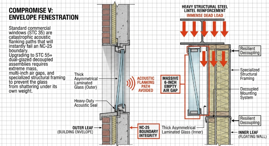
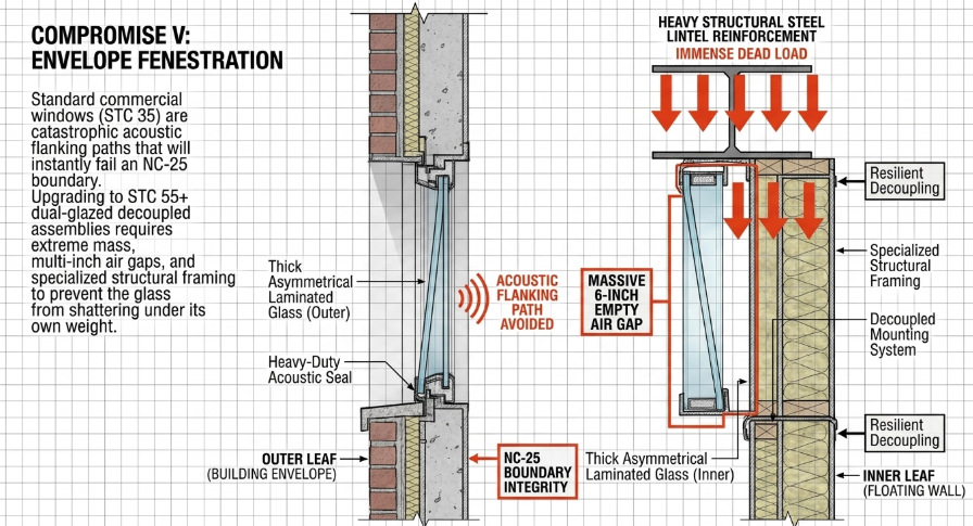
The final significant architectural compromise enacted when retrofitting a commercial office space into a high-density NC-25 environment involves the building envelope—specifically fenestration (windows and natural light). Standard commercial office buildings feature expansive exterior windows to provide natural light and aesthetic appeal. However, standard commercial dual-pane windows typically carry an STC rating of roughly 27 to 35. Soundproof Windows
An exterior window with an STC of 35 is a catastrophic flanking path for environmental noise, easily letting in the sounds of street traffic, sirens, aircraft, and rain. If the insulated MSM wall assembly is painstakingly designed to achieve STC 65, the presence of an STC 35 window will immediately degrade the composite transmission loss of the entire wall assembly, virtually guaranteeing failure of the NC-25 background noise threshold. Acoustical Society
Acoustic Glass Integration and Structural Limits
To retain natural light while achieving NC-25, the architect must specify the installation of specialized acoustic windows. To match the STC 55+ performance of the decoupled studio walls, acoustic windows require a custom dual-glazed configuration. Viracon This involves two unusually thick panes of asymmetrical laminated glass (to prevent sympathetic resonance), separated by a massive air gap that is often 4 to 8 inches deep. Soundproof Windows
The installation of these windows is highly complex. The inner pane must be mounted strictly to the floating inner wall leaf, while the outer pane mounts to the exterior building envelope, with a flexible neoprene or decoupled acoustic barrier bridging the gap to prevent rigid structural transmission. Overly Door Company The weight of these fixed acoustic windows is immense, often weighing hundreds of pounds, requiring heavy-duty structural lintel reinforcement in the wall framing to prevent the glass from shattering under its own weight. Overly Door Company Due to the prohibitive cost of engineering, manufacturing, shipping, and installing heavy STC 55 glass assemblies, many studio designers are forced to compromise by significantly reducing the size of the windows to mere slivers. Soundproof Windows
The Subterranean Feedback Loop
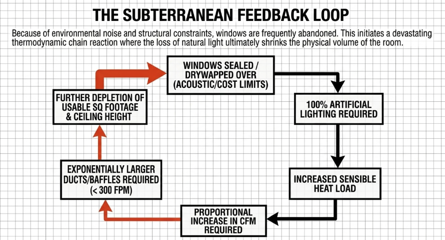
In extreme cases—such as when the commercial office building is located near a busy highway, an active subway line, or an airport flight path—the external acoustic pressure is so high that even specialized dual-pane acoustic windows cannot provide sufficient isolation. HVAC-eng In these scenarios, the ultimate architectural compromise is enacted: the existing commercial windows are permanently sealed, heavily insulated, and drywalled over. Soundproof Your Studio
The studio effectively becomes a subterranean-style bunker, entirely devoid of natural sunlight. This compromise triggers an immediate thermodynamic feedback loop. The lack of natural light forces a complete reliance on artificial lighting arrays. Soundproof Your Studio Even with modern LED technology, intense studio lighting contributes further sensible heat to the room, marginally increasing the Qsensible load. As demonstrated earlier in the mathematical analysis, an increase in Qsensible demands a proportional increase in CFM to remove the heat. Because the NC-25 rating strictly limits air velocity to a maximum of 300 FPM, any increase in CFM forces the HVAC ducts and baffle boxes to become even larger, further compressing the ceiling height and exacerbating every spatial compromise within the facility.
Conclusion
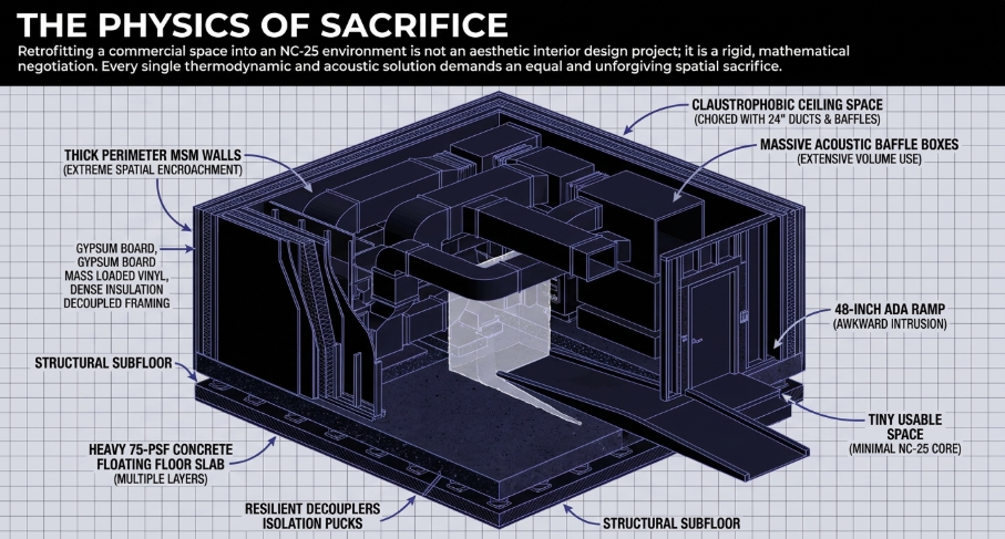
The successful engineering of a high-density, NC-25 recording studio within the confines of a standard commercial office space requires a masterful balancing of conflicting physical laws. The thermodynamic imperative to remove 35 to 70 watts per square foot of sensible heat generated by dense equipment arrays demands massive volumetric airflow. However, because the psychoacoustics of the NC-25 curve severely restrict this airflow to a maximum velocity of 300 FPM to prevent aerodynamic noise, the cross-sectional area of the HVAC ductwork must expand exponentially.
This inescapable fluid dynamic reality triggers a relentless cascade of architectural penalties. The massive low-velocity ducts and requisite acoustic baffle boxes dominate the ceiling plenum, forcing the finished ceiling height downward and compressing the volumetric acoustics of the room. Simultaneously, the necessity for low-frequency acoustic isolation requires the installation of dense floating floors, driving the floor elevation upward and introducing profound structural dead-load crises and ADA egress complications. Finally, the decoupling of the perimeter walls through Mass-Spring-Mass construction strips the space of its horizontal square footage, while the vulnerability of standard commercial fenestration often forces the complete abandonment of natural light.
Therefore, the retrofit of a commercial office space into an elite acoustic environment is never merely an aesthetic remodel; it is a rigorous, mathematically bound exercise in managing physical compromises, where every thermodynamic solution demands an equal and unforgiving spatial sacrifice.