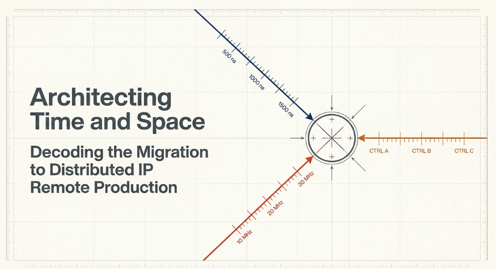
The Transition from Baseband SDI to IP-Distributed Workflows
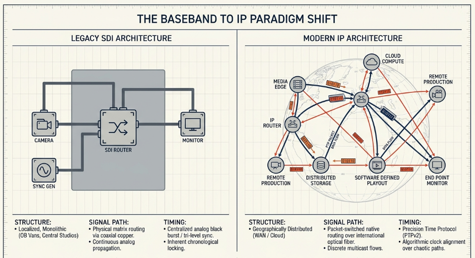
The broadcast engineering landscape is undergoing a fundamental paradigm shift, migrating from localized Serial Digital Interface (SDI) baseband routers to packet-switched Internet Protocol (IP) networks. Historically, the execution of live broadcast mixing-whether for televised sports, international news broadcasting, or large-scale live music events-required all discrete audio, video, and communications signals to be routed to a centralized, physical location. This localized architecture, typically embodied by the Outside Broadcast (OB) van or a dedicated local studio facility, required the mass physical transportation of specialized routing hardware, complex copper and coaxial cabling systems, and comprehensive engineering teams AIMS Alliance.
In a traditional SDI environment, signal synchronization was relatively straightforward. Timing was universally achieved by distributing a centralized analog black burst or tri-level sync signal via dedicated coaxial cabling to every endpoint in the facility. Because the cable lengths were fixed and the signal propagation was continuous and uninterrupted, endpoints such as cameras, video switchers, and audio consoles were locked to an identical, highly stable timing reference Cisco. The signals flowed chronologically, with the output of each device feeding directly into the input of the next through matrix routing switchers and patch bays SMPTE.
However, the advent of high-bandwidth Wide Area Networks (WAN), multiprotocol label switching (MPLS), and standard IP media protocols has enabled the deployment of distributed remote production models. In this modern architecture, the geographical link between the physical recording environment and the primary audio mixing console is effectively severed AIMS Alliance. Audio signals captured at a distant venue (for example, in Tokyo) can be digitized at the edge, encapsulated into IP packets, and routed natively over international fiber-optic links to a production facility situated thousands of miles away (such as in New York). There, the signals are mixed in real-time on a broadcast console and transmitted directly to the global delivery network The Broadcast Bridge.
This methodology maximizes physical resource utilization, dramatically reduces the carbon footprint associated with crew travel, and permits highly skilled operators to mix multiple disparate events in a single day without leaving their central facility. Broadcasters and production entities, such as TV 2 Norway and the WDR RegioNet in Germany, have successfully transitioned to fully IP-based audio platforms to avoid massive localized cabling and to integrate seamlessly into software-defined network topologies LAWO.
Despite its operational advantages, distributed IP production introduces severe engineering challenges regarding temporal alignment. In an asynchronous, packet-switched IP network, data is subject to variable routing paths, dynamic queuing delays at every switch, and transient network congestion. Maintaining deterministic timing across such a chaotic medium requires sophisticated protocol interventions. Achieving perfect synchronization in a distributed architecture mandates a multi-layered approach that addresses physical optical propagation delays, protocol-level clock alignment, hitless network redundancy, and human-machine interface latency compensation Microsoft.
Precision Time Protocol: Evolution and Mechanics
The precise synchronization of endpoints across a network is the foundational dependency for all subsequent IP media transport operations. Without a mathematically unified temporal framework, asynchronous audio and video packet streams cannot be accurately reassembled at the receiver, leading to severe lip-sync anomalies, phase cancellation in multi-microphone arrays, and catastrophic sample-slip artifacts in the final audio mix Ardour.
The Evolution of IEEE 1588
To address the stringent timing requirements of modern industrial and broadcast applications, the Institute of Electrical and Electronics Engineers (IEEE) developed the Precision Time Protocol (PTP) The Broadcast Bridge. While the earlier and universally adopted Network Time Protocol (NTP) provides millisecond-level accuracy suitable for general computing tasks and web servers, PTP was designed specifically for high-frequency trading, telecommunications, electric power distribution, and audiovisual networks requiring vastly superior temporal resolution Wikipedia.
The first iteration, IEEE 1588-2002 (PTP Version 1), was published in 2002 Wikipedia. However, the demands of the broadcasting and telecommunications sectors quickly necessitated enhancements, leading to the ratification of IEEE 1588-2008, known widely as PTP Version 2 (PTPv2) Wikipedia. It is critical to note that PTPv2 is not backward compatible with the 2002 version, requiring bridge infrastructure to allow legacy devices to function on modern networks Wikipedia. A subsequent update, IEEE 1588-2019, was published in November 2019 to include backward-compatible improvements to the 2008 publication Wikipedia. While PTP is sufficient for standard broadcast timing, extreme edge cases requiring sub-nanosecond accuracy (such as phase array antenna alignment) may utilize specialized initiatives like the White Rabbit Project Wikipedia. However, as demonstrated in corporate WAN field trials conducted by Endace, standard PTPv2 provides vastly superior synchronization compared to NTP, achieving sub-microsecond synchronization under ideal conditions across operational backbones Endace.
Delay Request-Response Mechanism
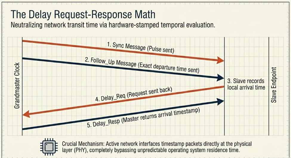
PTP operates on a hierarchical master-slave topology, relying on a designated Grandmaster clock to distribute timing reference data across the network The Broadcast Bridge. The protocol calculates timing by exchanging a sequence of carefully timestamped messages over User Datagram Protocol (UDP) ports 319 and 320 Wikipedia. The sequence relies on a delay request-response mechanism to continuously measure, evaluate, and compensate for the network's inherent latency Cisco.
The Grandmaster initiates the synchronization process by transmitting a Sync message to the network Cisco. In a two-step clock operation, this is immediately followed by a Follow_Up message containing the precise, hardware-stamped time of when the initial Sync message actually departed the master's physical interface Cisco. Upon receiving these packets, the slave device (e.g., a remote audio stage box or a central mixing console) records its local arrival time Cisco.
To calculate the exact round-trip propagation delay, the slave endpoint transmits a Delay_Req (Delay Request) message back to the master, noting its exact departure time Cisco. The master logs the exact arrival time of this request and transmits this timestamp back to the slave embedded within a Delay_Resp (Delay Response) message Cisco. By mathematically processing these four timestamps, the slave endpoint computes both the unidirectional path delay (assuming symmetrical transit times) and its specific offset from the master clock Cisco. This allows the slave to adjust its internal digital oscillator to perfectly mirror the Grandmaster's time, effectively synchronizing the local clock within nanoseconds of the reference Cisco.
With dedicated hardware-supported PTP implementations, active network interfaces timestamp packets directly at the physical layer (PHY) the exact moment they enter or exit the port Cisco. This hardware isolation eliminates the unpredictable software processing delays, or "residence time," introduced by the endpoint's central processing unit and operating system stack, enabling the highly precise generation of a predictable event clock The Broadcast Bridge. With this predictable clock, distributed playout servers and mixing nodes can execute programmatic automated switches (e.g., triggering regional ad insertions or audio scene changes) at exact future timestamps within a margin of one nanosecond, circumventing the need to rely on localized, reactive cueing signals over the WAN The Broadcast Bridge.
Media-Specific PTP Profiles: SMPTE ST 2059-2 and AES67
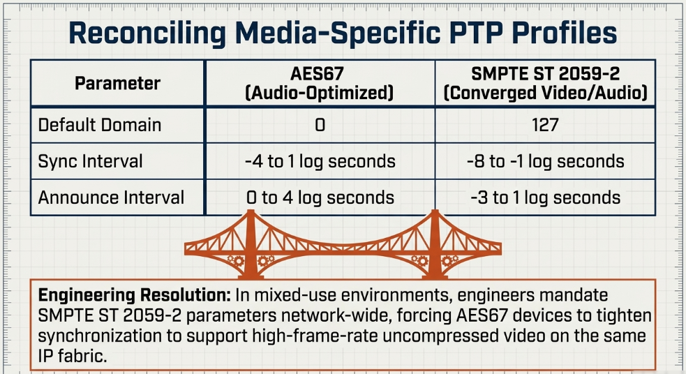
Because IEEE 1588-2008 is a generalized standard utilized across diverse industrial sectors, it incorporates a profile concept Wikipedia. A profile defines the specific operating parameters, optimal message rates, allowable options, and precise algorithms tailored to distinct use cases Wikipedia. In the professional audio and video broadcast sector, two prevailing PTP profiles dictate WAN media synchronization: AES67 and SMPTE ST 2059-2 Cisco.
The AES67 PTP profile was designed explicitly to facilitate bridging and interoperability between disparate Audio-over-IP (AoIP) networking solutions, such as Dante, RAVENNA, and Livewire+, and it specifies timing intervals optimized strictly for audio payloads. Conversely, the SMPTE ST 2059-2 profile, defined as part of the broader SMPTE ST 2110 suite for uncompressed professional media over IP, aligns PTP parameters to ensure that video frame boundaries, Digital Audio Reference Signals (DARS), and IP network timing are fundamentally, mathematically linked. Equipment operating within a converged remote production facility must therefore be carefully configured to reconcile these two distinct profiles.
The presence of conflicting default domain numbers-Domain 0 for AES67 versus Domain 127 for SMPTE ST 2059-2-necessitates careful network engineering. In mixed-use environments where audio and video must coexist on the same IP fabric, engineers typically standardize on the SMPTE ST 2059-2 profile parameters across all endpoints. This involves tightening the AES67 synchronization and announce intervals to support the significantly stricter requirements of combined high-frame-rate uncompressed video and high-sample-rate audio networks Dante.
The Best Master Clock Algorithm (BMCA)
To determine which device on the network acts as the primary timing reference, PTP utilizes the Best Master Clock Algorithm (BMCA) Wikipedia. The BMCA is a self-configuring, continuous mechanism that automatically evaluates all PTP-capable devices on a network segment based on the contents of their Announce messages (in PTPv2) or Sync messages (in PTPv1) Dante.
The algorithm determines the status of each PTP port, dictating whether it operates in a Listening, Follower (Slave), or Leader (Master) state Dante. Through this continuous polling, the BMCA ensures that the most accurate and stable clock in the domain becomes the Grandmaster RAD. If the current Grandmaster fails, the BMCA automatically evaluates the remaining clocks and transitions the next-best boundary clock or secondary master into the primary leadership role, preventing catastrophic timing loss across the production network RAD.
Grandmaster Architecture and WAN Synchronization
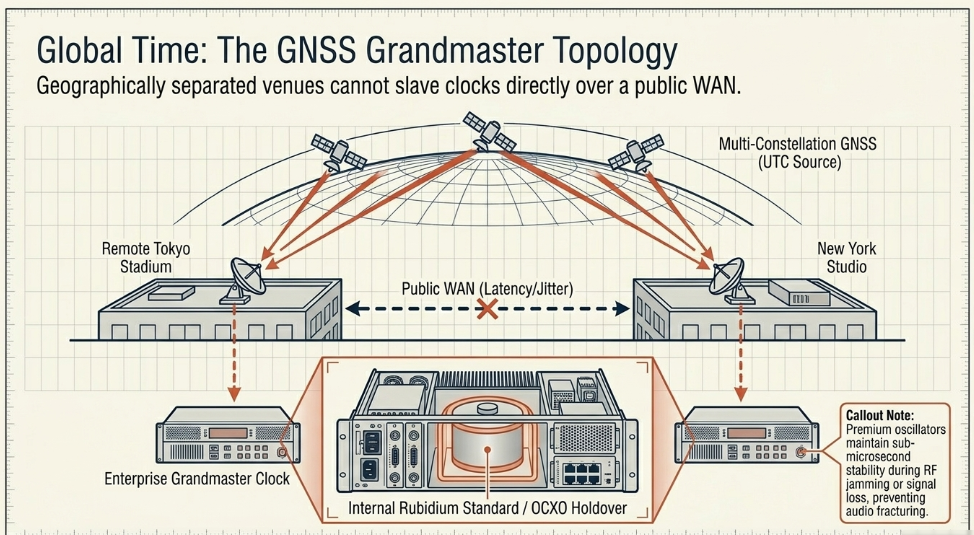
To maintain absolute temporal coherence between a remote recording venue and a central mixing studio separated by hundreds of miles, independent Grandmaster clocks must be deployed at both geographical locations Skyworks. Attempting to force a remote facility to slave its clock directly to the central studio's master over the fluctuating conditions of a public WAN is generally discouraged, as the extreme latency and jitter variations would severely degrade the precision of the offset calculations, leading to audio dropouts and phase issues Endace.
Instead, both Grandmaster clocks independently lock to a common, global external reference Endace. This global reference is universally derived from Global Navigation Satellite Systems (GNSS) RAD. By utilizing active antennas placed on facility rooftops with clear lines of sight, Grandmaster clocks receive highly accurate Coordinated Universal Time (UTC) signals from multiple satellite constellations concurrently, including the U.S. Global Positioning System (GPS), the Russian GLONASS system, and the European Galileo network RAD. This multi-constellation approach provides highly accelerated and highly precise time and positioning estimates Masterclock.
Field studies evaluating distributed synchronization, such as those utilizing simple Raspberry Pi hardware coupled with GNSS-HATs and low-cost active antennas, demonstrate the absolute viability of creating highly accurate Grandmaster clocks to serve localized subnets within a broader WAN topology Diva-portal.org. However, in mission-critical broadcast scenarios, enterprise-grade Grandmaster infrastructure is paramount.
Because GNSS signals are vulnerable to atmospheric interference, extreme weather events, intentional signal jamming, or physical line-of-sight obstructions, broadcast-grade Grandmaster clocks incorporate premium internal oscillators, such as rubidium atomic standards or Oven-Controlled Crystal Oscillators (OCXO) RAD. In the event of a total satellite signal failure or deliberate RF jamming, these advanced internal oscillators maintain the network's heartbeat RAD. They provide exceptional holdover capabilities, ensuring sub-microsecond stability over prolonged periods and keeping the distributed network completely synchronized without any access to the external UTC reference RAD. Once the GNSS signal is restored, the clock smoothly realigns to the satellite reference without causing sudden timing jumps that would fracture audio streams.
Navigating Network Topologies: Transparent and Boundary Clocks
Distributing PTP across a multi-hop, hierarchical IP network introduces a profound challenge: every active network element, such as a switch or router, fundamentally increases the propagation delay and introduces packet jitter as messages traverse internal physical backplanes and wait in QoS queues Endace. Left unmanaged, the cumulative jitter across a complex broadcast wide-area architecture would destroy the microsecond accuracy of the PTP offset calculations. To mitigate the devastating impact of switching and queuing latency, modern media IP networks strictly employ PTP-aware infrastructure operating as either Transparent Clocks or Boundary Clocks Endace.
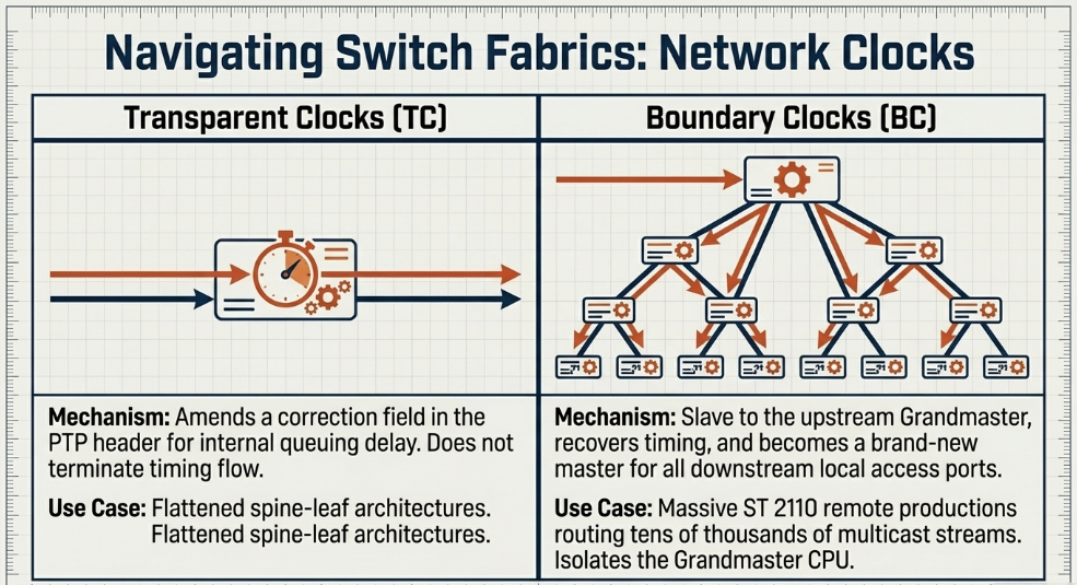
Transparent Clocks (TC)
A Transparent Clock acts dynamically upon the PTP packets passing through its network interfaces without terminating the timing flow Endace. When a Sync or Delay_Req message enters a TC-enabled switch, the hardware records the precise ingress time. Upon packet egress, the switch calculates its internal processing delay-known as the residence time-and dynamically modifies a specific correction field within the PTP packet header to reflect this localized delay Cisco.
By the time the PTP message reaches the slave endpoint at the edge of the network, the packet's metadata accurately reflects the total unmitigated transit time Embrionix. This mechanism effectively renders the intermediate network infrastructure mathematically invisible to the synchronization protocol, allowing the slave to perform highly accurate delay calculations Embrionix. In modern software-defined spine-leaf architectures, top-of-rack switches acting as Transparent Clocks ensure timing data flows fluidly between media nodes Embrionix.
Boundary Clocks (BC)
Conversely, a Boundary Clock terminates the PTP synchronization chain at the switch level Endace. A BC-enabled switch contains its own internal high-quality PTP oscillator The Broadcast Bridge. It acts as a standard slave to the upstream Grandmaster clock, recovering the timing signal, calculating the offset, and locking its internal oscillator to the UTC reference Riedel Communications. Once locked, the switch then assumes the role of an entirely new master clock for all downstream devices connected to its local access ports Endace.
While Transparent Clocks are effective for smaller, flattened topologies, Boundary Clocks are considered the superior and necessary architectural design for large-scale distributed broadcast networks spanning massive geographical areas. In immense SMPTE ST 2110 deployments routing tens of thousands of individual multicast streams, Boundary Clocks prevent multicast packet flooding by completely localizing PTP traffic within specific subnets. Furthermore, they drastically reduce the immense processing burden on the central Grandmaster, which would otherwise be forced to negotiate individual Delay_Req and Delay_Resp messages with thousands of endpoint microphones, cameras, and consoles simultaneously-a scenario that would cripple the Grandmaster's CPU Riedel Communications.
Audio-over-IP Protocols for Remote Production
With absolute temporal alignment established across the WAN, the physical transmission of the audio payload itself must be standardized. Traditional layer-2 protocols, while effective for isolated local environments, lack the routability required for long-distance WAN remote production. The industry has therefore standardized on Layer-3 Audio-over-IP (AoIP) protocols that encapsulate linear audio payloads into highly routable Real-time Transport Protocol (RTP) streams toncar.cz.
SMPTE ST 2110-30 and AES67 Interoperability
SMPTE ST 2110 represents a definitive departure from the legacy SDI methodology by discarding the concept of heavily multiplexed baseband signals Dante. Instead of embedding audio channels and ancillary data blindly within the vertical blanking intervals of a heavy video stream, ST 2110 utilizes a highly flexible essence-based architecture ENENSYS Technologies. It transmits uncompressed video (ST 2110-20), audio (ST 2110-30), and ancillary metadata (ST 2110-40) as entirely independent, discrete IP multicast flows Dante.
The audio transport specification, SMPTE ST 2110-30, is fundamentally derived from the AES67 standard Dante. In practice, ST 2110-30 is a carbon copy of AES67, acting as a bridging compliance mode, but with several restricted parameters designed to ensure absolute predictability and interoperability in high-stress professional broadcast environments Dante. Both protocols transport linear PCM audio mapped within RTP payloads, utilizing standard Internet Group Management Protocol version 2 or 3 (IGMPv2/3) for localized multicast subscription and routing across switch fabrics Juniper Networks.
To guarantee pristine interoperability across different manufacturers' mixing consoles, DSP engines, and physical stage boxes, SMPTE ST 2110-30 enforces strict conformance levels regarding audio formatting and packetization:
Level A: Enforces a baseline 48 kHz sampling rate, supports 1 to 8 audio channels per stream, and dictates packet times of exactly 1 millisecond Dante.
Level B: Incorporates Level A capabilities but mandates support for lower-latency 125-microsecond packet times, significantly accelerating the transmission rate Dante.
Level C: Incorporates both Level A and Level B capabilities while aggressively expanding the payload capacity to support up to 64 discrete audio channels per stream at the 125-microsecond interval Dante.
Session Description Protocol (SDP) Anatomy
The setup of an AES67 or ST 2110 stream necessitates the precise exchange of Session Description Protocol (SDP) files Dante. An SDP file contains the critical blueprint metadata required for a receiver to correctly ingest, decode, and align the incoming stream Dante.
This blueprint includes the sender's multicast IP group address, UDP port, specific audio encoding format (e.g., L24 for 24-bit linear PCM), sample rate, and channel count Dante. Crucially for remote production, the SDP file dictates the exact PTP reference clock identifier. Using syntax such as a=ts-refclk:ptp=IEEE1588-2008 accompanied by the localmac address of the sender, the SDP perfectly maps the RTP stream to the specific IEEE 1588 time domain Dante. This ensures that when the audio arrives at the distant mixing console, the timing relationships defined in SMPTE ST 2110-10 between the media clock, RTP timestamp, and PTP clock can be perfectly reconstructed Dante.
Layer 3 Spanning and Dante Domain Manager
While AES67 and SMPTE ST 2110 define the raw, open transport specifications, proprietary ecosystems like Audinate's Dante provide robust management layers that simplify complex IP routing, maintaining AES67 bridging modes for interoperability Dante. In local production networks, standard Dante architecture relies heavily on multicast PTP and generic broadcast discovery protocols (such as mDNS) RAVENNA Network. However, deploying native Dante or unmanaged AES67 across a routed WAN for remote mixing poses significant architectural hurdles, as core internet routers inherently block multicast traffic to preserve wide-area bandwidth Dante.
Furthermore, basic routing parameters can fracture timing. Native Dante PTP packets are typically dispatched by default with a Time To Live (TTL) value of 1 Reddit. A TTL of 1 deliberately restricts the packets to a single local subnet; the moment the packet hits the first edge router, it is discarded, destroying synchronization across the WAN Reddit. Overcoming this requires adjusting the TTL to higher values (e.g., 4) on specific hardware (such as Brooklyn II chipsets, rather than legacy Ultimo chips) or migrating to sophisticated enterprise architectures Reddit.
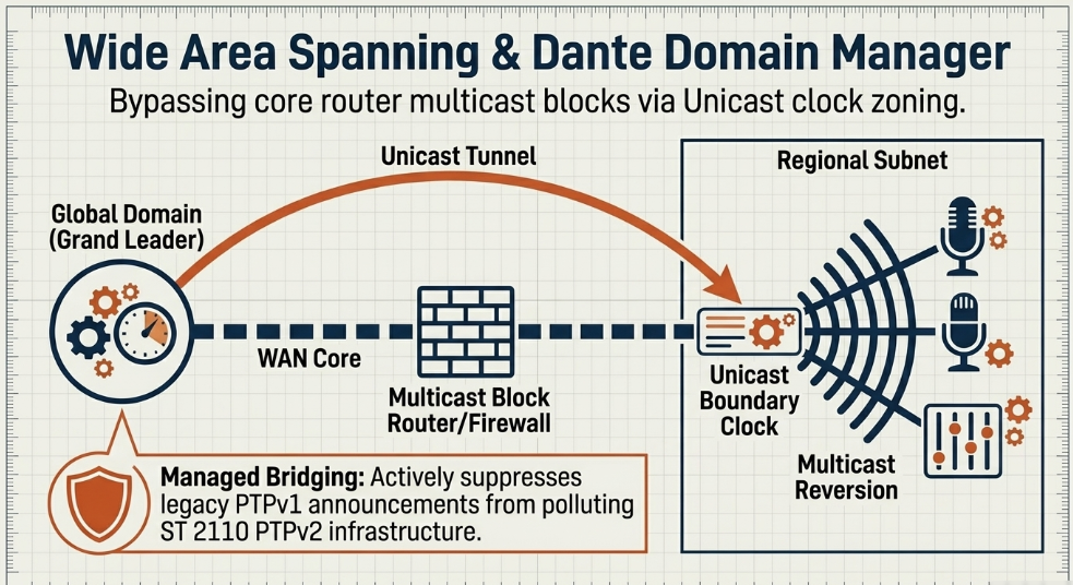
Broadcasters frequently utilize Dante Domain Manager (DDM), an enterprise-grade server application that permits AoIP networks to securely span multiple Layer 3 subnets across geographic distances Dante. DDM fundamentally alters the clocking architecture to support WAN distribution by implementing Unicast PTP clocking and Clock Zoning Dante.
Under this architecture, the WAN is divided into independent clocking zones corresponding to distinct geographical subnets Audinate. A single Grand Leader clock is elected for the entire global domain. DDM then automatically (or manually) designates one specific endpoint device within each remote subnet to act as a Unicast Boundary Clock Audinate. The central Grand Leader transmits PTP timing data via unicast, point-to-point IP connections directly to these regional boundary devices across the WAN link, bypassing the multicast restrictions of the core routers Audinate.
Upon receiving the unicast timing data, the regional boundary clock reverts to acting as a standard multicast master for its local subnet, effortlessly synchronizing all local microphones, stage boxes, and monitors Reddit. This intricate topology guarantees perfectly synchronized, phase-coherent clocking across geographically isolated venues while adhering strictly to WAN bandwidth and multicast limitations. Furthermore, DDM provides managed bridging, actively suppressing legacy PTPv1 multicast announcements from polluting the highly sensitive ST 2110 PTPv2 infrastructure, ensuring that legacy and modern protocols can coexist without inducing synchronization collapse Dante.
Extensive proof-of-concept deployments, such as a global AES67-over-WAN demonstration connecting AWS cloud infrastructure in Virginia and Frankfurt with physical broadcast sites in Lausanne, Mittweida, Ottawa, and Grenoble, validate the capacity to route uncompressed, perfectly clocked audio across public internet and cloud infrastructure over immense geographical distances using these advanced techniques AIMS Alliance.
Optical Fiber Physics and Propagation Latency
When pristine, uncompressed audio signals traverse hundreds or thousands of miles between a live event and a remote mixing console, the immutable laws of physics dictate an unavoidable propagation delay. Effectively compensating for this latency and aligning disparate audio sources requires a highly detailed understanding of optical transport mechanics.
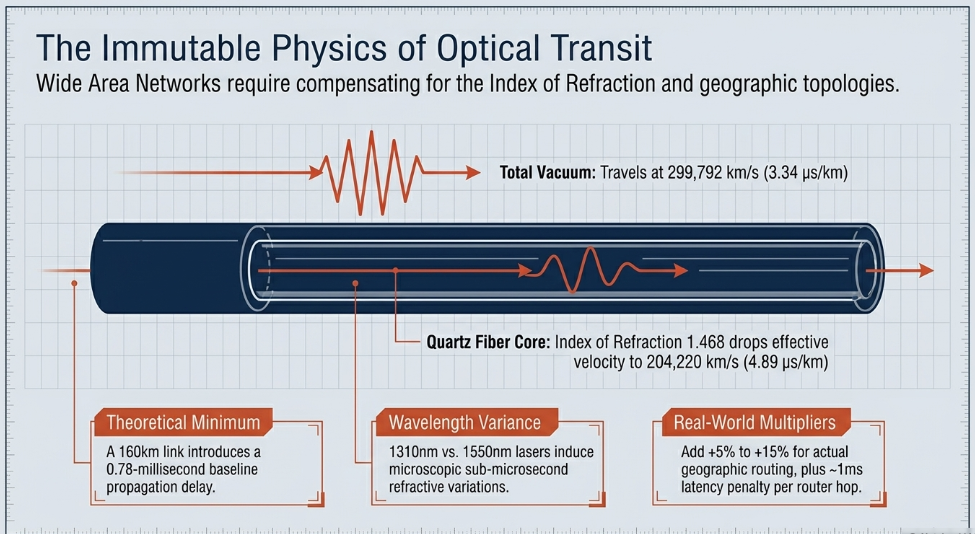
In a total vacuum, electromagnetic radiation travels at exactly 299,792.458 kilometers per second (or roughly 3.34 microseconds per kilometer) M2 Optics. However, within the dense glass core of a single-mode optical fiber, light propagates substantially slower due to the material's specific Index of Refraction (IOR) DWDM.ME. For standard telecommunications quartz fiber, the IOR is approximately 1.468 DWDM.ME.
To calculate the precise theoretical baseline latency of an optical transmission path, the speed of light in a vacuum is divided by the IOR, yielding an effective transmission velocity of roughly 204,220 km/s M2 Optics. Consequently, it takes light approximately 4.89 microseconds to traverse one kilometer of optical fiber M2 Optics. The specific wavelength of the transmission laser also induces microscopic variations. For example, transmitting a 1310nm laser over 100 kilometers of G.652 standard fiber yields a theoretical latency of 489.34 microseconds, whereas utilizing a 1550nm wavelength over the identical medium results in 489.67 microseconds M2 Optics. While a 0.33-microsecond differential appears entirely negligible in standard networking, in tightly coupled, phase-aligned remote antenna arrays or deeply integrated multi-microphone setups, understanding these refractive variations becomes critical for phase coherency M2 Optics.
Therefore, if a remote sports venue is located 100 miles (160 kilometers) from the central mixing studio, the absolute minimum, theoretically perfect one-way fiber propagation delay is approximately 0.78 milliseconds. However, real-world wide-area networking mandates several additional calculations WintelGuy.com. First, optical cables are rarely laid in perfectly straight lines; they follow geographic topographies, local access loops, road networks, and rail lines WintelGuy.com. Network engineers must apply a "fiber path adjustment," often adding 5% to 15% to the total physical geographic distance to account for the actual cable routing WintelGuy.com. Furthermore, every active routing hop, firewall packet inspection, and network address translation (NAT) protocol adds internal equipment latency-typically estimated at roughly 1 millisecond per sophisticated network device in the chain WintelGuy.com. Variations in environmental temperature and physical stress can also alter the refractive index and fiber length dynamically, necessitating continuous monitoring techniques such as Correlation Optical Time Domain Reflectometry (C-OTDR) to measure propagation delay asymmetry accurately in critical environments like 5G front-haul or PTP distribution networks arXiv.
Path Delay Variation, Jitter Buffers, and Link Offsets
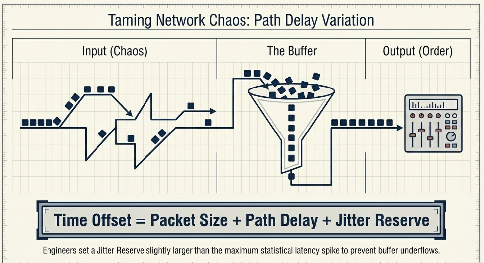
While the physical optical propagation delay dictates the absolute baseline transit time, the asynchronous nature of packet-switched networking introduces highly dynamic temporal variables. As Real-time Transport Protocol (RTP) packets traverse disparate WAN nodes, they experience Path Delay Variation (PDV), commonly referred to as network jitter Clear-Com.
Because individual IP packets may be temporarily held in router queues during bursts of high traffic or take slightly divergent routing paths, they arrive at the destination receiver asynchronously, slipping out of their perfectly metered generation intervals. If an audio stream is fed directly into a Digital-to-Analog Converter (DAC) or DSP mixing engine without any temporal smoothing, these arrival variations will cause severe audio distortion, packet dropouts, buffer underflows (where the engine needs to process audio but the packet hasn't arrived), and buffer overflows (where packets arrive too fast and are discarded) toncar.cz.
Additionally, jitter is not exclusively a product of network transit; it can originate at the source. If audio is generated by software systems (like Interactive Voice Response (IVR) or voice mail applications) relying on a standard computer's internal clock rather than a highly stable, dedicated sound card oscillator, extreme localized jitter is introduced before the packet even hits the network toncar.cz.
Jitter Buffer Management
To rectify network and source jitter, the receiver endpoint implements a jitter buffer-a localized, temporary memory store that queues incoming RTP packets, corrects out-of-sequence errors utilizing the embedded RTP sequence numbers, and releases the audio data to the mixing core at a perfectly constant, evenly spaced interval Cisco Meraki. There are two primary buffer architectures:
Dynamic Jitter Buffers: These algorithms adapt their size continuously based on real-time evaluation of current network conditions and packet arrival patterns, providing a flexible safety net toncar.cz.
Static Jitter Buffers: These maintain a fixed size regardless of network fluctuations NextPointe. While less adaptable, professional broadcast environments typically rely on meticulously calculated static buffers to maintain highly predictable, deterministic overall latency, accepting the risk that severe anomalies might cause momentary drops rather than allowing the buffer size to fluctuate and constantly shift the audio phase relationship NextPointe.
Increasing the size of the jitter buffer dramatically improves transmission resilience by absorbing larger latency spikes, but it directly inflates the overall delay of the system toncar.cz. If an engineer sets a 50-millisecond buffer, the audio signal is inherently delayed by an additional 50 milliseconds before it even enters the mixing console toncar.cz.
Calculating AES67 Link Offsets
To achieve perfect phase-coherency between diverse audio channels arriving from different remote microphones, the receiving mixing console must employ explicit link offset parameters. The link offset fundamentally represents the total duration from the exact moment an audio sample is captured at the remote microphone to the moment it is released from the receiver's jitter buffer into the mix bus Tieline.
In AES67 network devices (such as Lawo Power Cores or Tieline codecs), this parameter is calculated via a highly specific architectural formula: Time Offset = Samples per Frame (Packet Size) + Path Delay + Jitter Reserve Lawo.
The Jitter Reserve is a highly configurable metric derived from evaluating the characteristics of the specific network path Lawo. Advanced network administrators classify routing paths based on distance, jitter variance, and device count. A Class 1 path denotes direct, highly stable connections over a single local switch, requiring minimal jitter reserve Lawo. Conversely, a Class 5 path represents highly complex, distant WAN distribution passing through multiple edge routers, service providers, and firewalls, demanding a substantial reserve to prevent packet loss during momentary wide-area congestion Lawo. By analyzing the statistical variations in the path delay, audio engineers configure a generalized link offset that is slightly larger than the absolute maximum latency spike statistically observed on the network, guaranteeing pristine, uninterrupted audio continuity Tieline.
Quality of Service and Video Traffic Shaping (ST 2110-21)
In a shared wide-area network infrastructure, uncompressed AoIP packets compete directly with massive file transfers, control data, external internet traffic, and bandwidth-heavy uncompressed video ENENSYS Technologies. Because real-time professional audio is hypersensitive to packet loss and completely unable to tolerate the high retransmission latency of standard TCP connections-it relies entirely on UDP transport mechanisms combined with rigid Quality of Service (QoS) frameworks GIAC.
Differentiated Services Code Point (DSCP) Implementation
To ensure audio and timing packets are prioritized across the WAN, edge devices use Differentiated Services Code Point (DSCP) markings within the IP header to categorize and prioritize traffic Dante. Following broadcast engineering best practices, AES67, ST 2110, and Dante implementations assign highly specific QoS priorities:
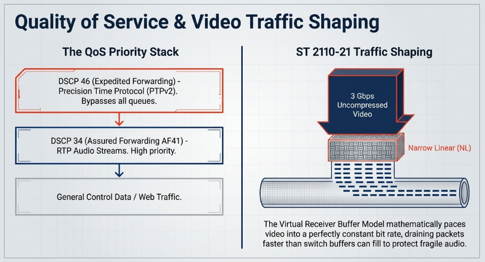
Precision Time Protocol (PTPv2): Assigned a DSCP value of 46, designated as Expedited Forwarding (EF) Dante. This guarantees that master clock sync messages bypass all internal switch queues, moving instantly through the network to preserve sub-microsecond timing accuracy Dante.
RTP Media Streams: Assigned a DSCP value of 34, categorized as Assured Forwarding (AF41) Dante. This strictly prioritizes real-time audio payloads above generalized web data or control traffic, but keeps it functionally below the critical PTP heartbeat Dante.
SMPTE ST 2110-21 Traffic Shaping
While QoS protects audio from generalized data, it cannot protect the network from the sheer volume of uncompressed video if left unchecked. A single 1080p video stream can consume 1.5 to 3 Gigabits per second. If a video sender dispatches these massive frames in sudden, localized bursts, it will instantly overflow the buffers of the core WAN routers, causing the indiscriminate dropping of high-priority audio and PTP packets Wikipedia.
To prevent this catastrophic network collapse, the SMPTE ST 2110 suite includes ST 2110-21, a standard specifically detailing the traffic shaping and delivery timing models required for real-time media Wikipedia. ST 2110-21 defines three distinct classes of transmitting devices based on their transmission timing behavior:
Narrow Linear (NL): These senders transmit video data at a perfectly constant, mathematically rigid bit rate, smoothing the traffic over the entire frame duration to minimize network buffer utilization Wikipedia.
Narrow (N): These senders pace traffic smoothly but may temporarily suspend transmission during the vertical blanking intervals (a relic of SDI timing architectures) Wikipedia.
Wide (W): These senders adhere to significantly less rigorous transmission timing requirements, often utilized in software implementations or non-real-time virtualized solutions Wikipedia.
The standard ensures network stability by mandating that high-volume ST 2110 video streams rely on strict mathematical formulas (incorporating active pixels and frame rates, e.g., 1080/1125 at 59.94Hz) to pace packet delivery SMPTE. By adhering to a Virtual Receiver Buffer Model (where packets enter and leave the receiver buffer immediately without underflow or overflow) or a Network Compatibility Model (where receivers guarantee draining packets faster than the switch buffers fill), ST 2110-21 traffic shaping guarantees that the underlying IP network remains stable, thereby protecting the highly fragile, latency-sensitive audio streams traversing the same fiber optic links The Broadcast Bridge.
Hitless Redundancy and Error Correction
The ultimate failsafe against physical link degradation, accidental fiber cuts, and optical hardware failure in remote production is the implementation of SMPTE ST 2022-7 Seamless Protection Switching, colloquially referred to in the industry as "hitless merging" Clear-Com.
SMPTE ST 2022-7 Mechanics
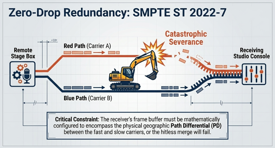
This standard demands that the sending device (e.g., the remote stage box) duplicate the critical RTP media stream perfectly at the source Clear-Com. These two identical packet streams are then transmitted simultaneously across entirely physically diverse, air-gapped WAN infrastructures often provisioned through separate, competing telecommunications carriers (e.g., a "Red" path via AT&T and a "Blue" path via Verizon, or BT and Virgin Media in the UK) RIST Forum.
At the receiving studio console, an algorithmic hitless reconstruction module analyzes both incoming data streams. By inspecting the embedded sequence numbers within the RTP headers (SSRC field verification), the receiver seamlessly buffers and selects the healthiest packet arriving from either the Red or the Blue path, assembling a single, flawless output stream at the datagram level Clear-Com. If a backhoe severs the primary fiber trunk 200 miles away, the system simply continues ingesting the identical sequence packets arriving via the secondary carrier without a single millisecond of audio interruption or dropout Clear-Com.
It is crucial to note that simply creating two independent transport sessions over two ISPs-referred to as "naive 2022-7"-does not constitute true hitless switching. Independent sessions lack synchronous input buffers and sequence awareness, leading to wasteful retransmissions and failed merging RIST Forum.
Path Differential (PD) and Receiver Buffers
Implementing true ST 2022-7 across a wide-area network necessitates extreme vigilance regarding Path Differential (PD) DekTec. Because the diverse "Red" and "Blue" WAN routes will inevitably possess dramatically different physical geographic lengths, routing complexities, and transit speeds, packets from the faster, shorter route will arrive significantly earlier than their exact duplicates on the slower route DekTec.
The receiving switch or console must utilize dedicated, adaptive buffers to temporarily hold the early-arriving packets until their lagging counterparts either arrive or are deemed permanently lost RIST Forum. The ST 2022-7 standard calculates this through the Maximum Differential (MD), defined as the latency from transmission to reconstructed output minus the earliest time a packet can arrive SMPTE.
If the receiver's ST 2022-7 frame buffer is configured too small to encompass the physical delay difference between the two carriers, the hitless switching mechanism will fail catastrophically, resulting in severely jerky or dropped audio and black video SMPTE. For example, Riedel's MediorNet implementation utilizes WAN jitter buffers to handle ST 2022-7 differentials with a maximum jitter tolerance of up to 120 milliseconds Riedel. Network engineers must meticulously calculate fiber distances and ping latencies for both redundancy paths to ensure the differential falls well within the receiver's hardware buffer capabilities, applying network emulators (like Calnex SNE) to inject burst packets, range delays, and reordered packets to validate buffer sufficiency prior to the live broadcast Calnex.
Forward Error Correction (FEC) and ARQ Strategies
In topologies where dedicated dual-path 2022-7 provisioning is economically infeasible or physically impossible, organizations may utilize Hybrid Forward Error Correction (FEC) combined with Automatic Repeat reQuest (ARQ) strategies Microsoft. FEC algorithms mathematically interleave parity packets into the outgoing media stream Microsoft. If an audio packet is dropped during transit, the receiver can utilize the surrounding parity data to reconstruct the missing packet mathematically, completely avoiding the need to request a retransmission from the sender Microsoft.
While implementing advanced hybrid FEC-ARQ protocols adds computational overhead, preempting original data packets with strategic FEC blocks fundamentally reduces the devastating delay spikes typically associated with standard ARQ protocols, which force the system to wait for a dropped TCP packet to be acknowledged, requested, and re-transmitted across hundreds of miles of fiber Microsoft.
Software-Defined Networking (SDN) and NMOS Orchestration
Scaling an IP media architecture to encompass entire buildings and multi-national remote venues involves managing upward of 100,000 distinct, interrelated multicast connections The Broadcast Knowledge. Configuring these complex flows manually via legacy IP addressing techniques and manual SDP file pasting is operationally untenable in a live environment RAVENNA Network. Modern WAN remote production relies heavily on the Advanced Media Workflow Association (AMWA) Networked Media Open Specifications (NMOS) suite to discover, orchestrate, and patch media streams automatically Promwad.
The NMOS Specification Suite
NMOS provides a vendor-agnostic control layer that functions above the ST 2110 transport plane, ensuring that equipment from different manufacturers can interface seamlessly Promwad. The architecture is defined across several critical specifications:
When a new audio endpoint, or "Node," boots on the network, it utilizes IS-04 to locate a centralized IS-04 Registration and Discovery System (RDS) database, typically via DNS-SD or mDNS Promwad. The Node registers its IP addresses and capabilities, listing itself as a Sender, Receiver, or both Promwad. Broadcast controllers query this registry via RESTful APIs to maintain a dynamically updated inventory of all available resources across the entire WAN facility, eliminating spreadsheets and enabling instant resource visibility Promwad.
To physically route the audio, the system utilizes IS-05 Scribd. A centralized software controller interacts with the IS-05 Connection API on a specific Receiver device, providing it with the precise transport parameters (via an SDP payload) of the desired Sender Promwad. The API utilizes a sophisticated two-stage process: staging the connection parameters first, and then executing a delayed, synchronized activation Promwad. This allows operators to pre-stage massive routing changes-known as "salvos"-and trigger them instantaneously across multiple remote venues simultaneously Promwad. Because technology lifecycles vary, NMOS embeds multi-version support, allowing newer v1.2 controllers to issue downgrade queries to orchestrate older v1.1 nodes without degrading the entire system's functionality AIMS Alliance. Advanced implementations even integrate NMOS APIs directly into visual programming tools like Node-RED, utilizing custom node-red-contrib-nmos nodes to create custom UI dashboards for matrix switching Node-RED Forum.
SDN Orchestration via VideoIPath
To synthesize device-level NMOS control with the active IP routing infrastructure, organizations deploy overarching broadcast control platforms like Nevion VideoIPath IABM. Integrating tightly with underlying switch fabrics using open APIs-such as Arista's Extensible Operating System (EOS)-these orchestration engines provide genuine Software-Defined Networking (SDN) Nevion.
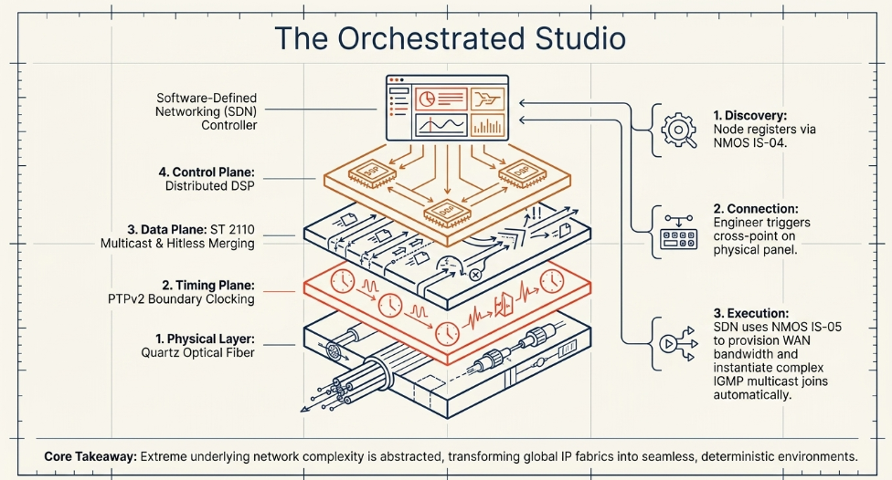
When a sound engineer presses a button on a hardware control surface to route a remote microphone to a fader, the SDN controller intercepts this request The Broadcast Knowledge. Rather than allowing the local switch to make a blind routing decision, the SDN controller evaluates the entire WAN topology, dynamically calculates the most efficient, deterministic IP path across the spine-leaf switch architecture, provisions the necessary bandwidth, and instructs the network hardware directly to instantiate the multicast flow The Broadcast Knowledge.
This abstracting of complex IGMP multicast joins, IP routing tables, and VLAN management allows broadcast operators to manage wide-area infrastructure using familiar, intuitive matrix router interfaces The Broadcast Knowledge. Broadcasters like WDR RegioNet have successfully deployed Nevion VideoIPath within advanced Docker clusters to orchestrate Arista switches and Lawo PowerCores simultaneously, ensuring high fail-safety and operational flexibility across 16 distinct geographic locations via SDN containerization Digital Media World.
Console Architecture and Distributed Digital Signal Processing
Resolving the complex physics of fiber optics and IP networking addresses the survival and synchronization of the audio signal. However, integrating that signal effectively into a live, fast-paced broadcast mix introduces severe human-computer interaction challenges that traditional consoles cannot overcome.
The Problem of Human Control Latency
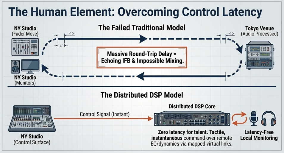
In localized studio environments, an audio engineer pushes a physical motorized fader on their desk, and the console's Digital Signal Processing (DSP) engine reacts instantly to alter the volume Scribd. In a true remote production scenario, the audio DSP is physically located at the remote venue hundreds or thousands of miles away to minimize the delay of the actual microphone signals entering the system. Consequently, moving a physical fader on a control surface in the central studio results in a massive operational delay Calrec Audio Ltd.
The control message must travel over the WAN to the remote location, the remote processor must apply the volume change, and the newly altered audio stream must travel all the way back over the WAN before the engineer actually hears the result in their studio monitors Calrec Audio Ltd. This round-trip latency severely impedes the operator's ability to mix highly dynamic content, such as live sports or musical performances, as their physical reactions are continuously out of phase with the auditory feedback Calrec Audio Ltd.
Furthermore, if a presenter or musician located at the remote venue is relying on an Interruptible Foldback (IFB) earpiece or stage monitors fed from the central studio, the round-trip latency of the network will cause a disorienting, echoing delay. The talent speaks into the microphone, the signal travels to the central studio, is processed, and travels back to their ear-often hundreds of milliseconds later-rendering it physiologically impossible for them to speak or perform coherently The Broadcast Bridge.
Distributed Remote Production Engines
To eradicate control latency and local monitoring delays, console manufacturers have pioneered distributed, highly virtualized DSP architectures. Instead of relying solely on massive central processing units, remote production relies on localized processing nodes deployed at the distant physical venue, combined with advanced remote-control protocols acting across the WAN Calrec Audio Ltd.
Systems such as the Calrec RP1 or Lawo's Power Core RP function as compact (e.g., 2U footprint), high-powered remote production units capable of processing immense amounts of audio directly on-site at the remote venue. The RP1 core operates at 48kHz and supports up to 96 legs as mono, stereo, or 5.1 input channels, 24 legs as Auxes, and 96 legs as Mix-Minus outputs. By keeping this critical DSP localized, these devices generate latency-free monitor mixes, IFB feeds, and automated commentary mixes for the on-site talent with absolutely zero noticeable delay Calrec Audio Ltd.
The audio engineer situated in the central studio utilizes their primary, full-scale broadcast console-such as the Calrec Argo (Q, S, or M), Artemis, Apollo, or the Lawo mc²56-to control this distant hardware via tightly integrated virtual IP links. Using highly optimized proprietary control protocols like Calrec's True Control 2.0 or Lawo's RPx framework, specific channel strips and physical faders on the studio surface are dynamically mapped to directly manipulate the DSP parameters running on the remote node hundreds of miles away Calrec Audio Ltd.
This framework grants the operator full, tactile command over remote equalization, dynamics processing (compressors, limiters, expanders, gates), routing, automixers, and path delay adjustments without the sluggishness of traditional VNC mirroring or parallel controlling limitations. A single controller console can simultaneously manage up to five independent units across different global locations, enabling massive live distributed workflows utilizing cloud-based DSP engines like Calrec ImPulse Calrec. Simultaneously, the remote unit packages the fully processed, latency-free mix and embeds it securely into standard backhaul pipelines-often marrying it directly to the returning SDI or ST 2110 video feed-eliminating complex synchronization differentials for the final transmission.
Phase Alignment and Automated Lip-Sync Compensation
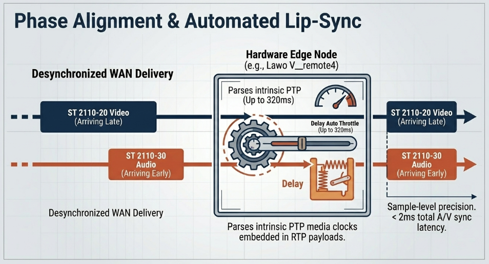
In environments where audio and video signals are processed via divergent WAN paths, aligning the auditory and visual elements represents the final, critical stage of latency management LAWO. Advanced edge devices, such as the Lawo V_remote4, provide specialized variable hardware delay lines to counteract processing desynchronization and ensure flawless lip-sync LAWO.
These dedicated processing nodes support immense architectural delay buffering, offering up to 320 milliseconds of audio delay and up to 8 frames of video delay LAWO. This massive buffer allows broadcast engineers to manually dial in exact sample-level offsets to achieve perfect phase alignment between parallel microphone inputs or correct divergent video processing paths LAWO. The hardware includes WordCLK inputs/outputs for precision audio phase alignment and Genlock capabilities tying directly to IP PTP master clocks, allowing simultaneous embedding, de-embedding, and Sample Rate Conversion (SRC) with an overall Audio/Video synchronization latency of less than 2 milliseconds.
Crucially, automated compensation modes dramatically simplify operations during live broadcasts LAWO. By parsing the intrinsic timestamps embedded within both the ST 2110-20 video payloads and the ST 2110-30 audio payloads, hardware algorithms can extract the original PTP timing differential. Utilizing settings like "Delay Auto," the infrastructure automatically evaluates the temporal gap and dynamically throttles the audio delay buffer to perfectly mirror the prevailing video latency LAWO. This automated lip-sync management guarantees pristine synchronization upon final broadcast distribution, regardless of real-world fluctuations, path delay variations, or jitter buffer adjustments occurring dynamically within the optical transport networks LAWO.