Introduction: The Broadcast Technology Paradigm Shift
The professional broadcasting and live media production industry is currently traversing the most profound infrastructural paradigm shift since the transition from analog to digital signaling.
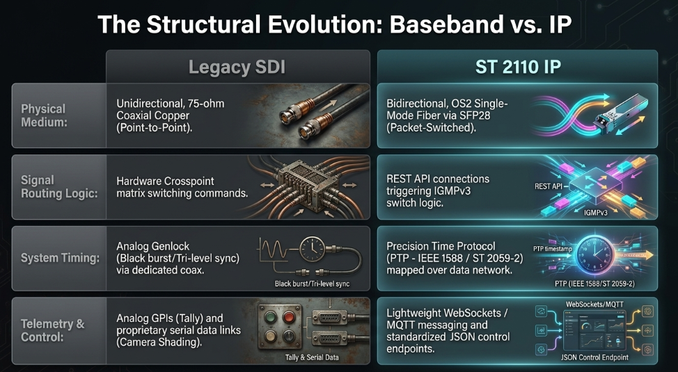
For decades, the foundational bedrock of broadcast architecture has been the Serial Digital Interface (SDI), a suite of standards governed by the Society of Motion Picture and Television Engineers (SMPTE) that dictates the point-to-point transmission of uncompressed video, embedded audio, and ancillary data over highly specialized 75-ohm coaxial cabling.
While SDI is fundamentally reliable and natively provides near-zero latency, it is an inflexible, unidirectional, and hardware-constrained technology. As the industry moves aggressively toward uncompressed 4K Ultra High Definition (UHD) video, High Dynamic Range (HDR) formats, and distributed remote production models, the inherent limitations of SDI baseband routing have become critical operational bottlenecks. (Key Code Media)
In response to these hardware constraints, the broadcast sector is rapidly adopting the SMPTE ST 2110 suite of standards, an architecture that facilitates the transmission of professional media over managed Internet Protocol (IP) networks. Awarded a 2025 Emmy for Outstanding Achievement in Engineering, Science & Technology, ST 2110 completely abandons the rigid physical crosspoint matrices of legacy broadcast facilities in favor of Commercial Off-The-Shelf (COTS) IT network switches and advanced Multicast routing protocols. When deployed over high-capacity 25 Gigabit Ethernet (25GbE) optical fiber connections, ST 2110 enables the simultaneous, bidirectional transmission of uncompressed 4K video, multitrack audio, return video feeds, tally light telemetry, and remote camera control protocols over a single physical strand. (COEX Wiki)
This comprehensive report provides an exhaustive technical analysis of how the SMPTE ST 2110 standard manages complex, multi-signal broadcast camera chains over 25GbE links. By systematically deconstructing the underlying physical layer transport mechanisms, the essence-based payload architecture, the mathematical realities of bandwidth utilization, and the critical role of the Advanced Media Workflow Association (AMWA) Networked Media Open Specifications (NMOS) control plane, this analysis contrasts the modern IP approach with the legacy constraints of SDI. The synthesis of these interconnected technologies represents a quantum leap in production flexibility, fundamentally transforming broadcast facilities from bespoke physical hardware installations into software-defined, hyper-converged data centers. (Qvest)
The Historical Progression of Camera Transmission Architectures
To fully comprehend the significance of the 25GbE ST 2110 architecture, it is necessary to examine the historical evolution of broadcast camera signal transmission. Live production camera chains are structurally complex entities. A broadcast camera head is not merely a video originator; it is a bidirectional communication hub that must simultaneously send high-resolution sensor data to the production switcher, receive return video feeds for the operator's viewfinder, facilitate continuous two-way intercom audio, illuminate tally lights to indicate on-air status, and receive continuous remote shading and iris adjustments from a dedicated Camera Control Unit (CCU). (Panasonic Connect)
In the earliest days of electronic live television, this immense signal routing requirement was solved through brute force. Camera heads were tethered to their respective base stations via massive multicore cables, where every individual signal-video, power, audio, and control-was mapped to a discrete, dedicated copper wire within the cable jacket. (Panasonic Connect) These multicore cables were tremendously heavy, highly susceptible to signal degradation, and dangerously fragile. (Panasonic Connect)
A significant evolution occurred around 1970 with the introduction of the Philips LDK 5 camera system, which pioneered Triax cable technology. (SMPTE) Triax allowed multiple analog signals to be multiplexed onto a single coaxial-style cable utilizing frequency carriers, earning a Technical Emmy in 1991 for its revolutionary impact on outside broadcasting. (SMPTE) As television transitioned into the digital high-definition era, bandwidth requirements outpaced the physical capacity of copper Triax. (SMPTE) The industry standardized upon the SMPTE 311M hybrid fiber cable. (Panasonic Connect) The SMPTE 311M specification utilizes a composite jacket housing two single-mode optical fibers to carry multiplexed high-bandwidth digital video and data, running alongside four heavy copper wires solely responsible for delivering high-voltage electrical power from the CCU up to the camera head. (Panasonic Connect)
While SMPTE 311M resolved the distance and bandwidth constraints between the camera head and the base station, the core routing infrastructure of the broadcast facility remained anchored to the Serial Digital Interface. (Panasonic Connect) The CCU, residing in an equipment rack, was forced to de-multiplex the optical signal and break it out into numerous physical SDI cables to interface with the central router. (Sony Pro)
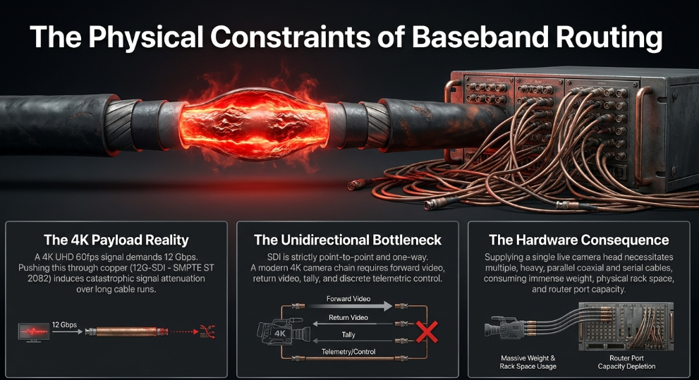
The evolution of SDI itself illustrates the relentless demand for bandwidth. Originally standardized in 1989 as SMPTE 259M, Standard Definition SDI (SD-SDI) operated at 270 Mbps. (Castr) The advent of High Definition required HD-SDI (SMPTE 292M) at 1.485 Gbps, followed by 3G-SDI (SMPTE 424M) at 2.97 Gbps to support 1080p video at 60 frames per second. The transition to 4K UHD resolutions forced the creation of 12G-SDI (SMPTE ST 2082), pushing 12 Gbps of data through a single copper coaxial cable. However, pushing 12 Gbps through copper physics severely limits cable lengths before catastrophic signal attenuation occurs. (Packet Storm) Furthermore, because SDI is strictly unidirectional, a 4K camera chain requiring forward video, return video, and discrete telemetric control necessitates multiple heavy coaxial cables running parallel to one another, consuming vast amounts of physical space, weight, and router port capacity. (Key Code Media)
The Physical Layer Paradigm Shift: 12G-SDI versus 25 Gigabit Ethernet
The architectural response to the physical and spatial limitations of 12G-SDI is the adoption of Commercial Off-The-Shelf Ethernet networking, explicitly leveraging 25 Gigabit Ethernet (25GbE) physical layer infrastructure. Rather than utilizing bespoke broadcast cables, ST 2110 workflows operate over standard IT network topologies utilizing small form-factor pluggable (SFP28) optical transceivers.
Table 1: Historical comparison of primary broadcast physical layer transmission standards, highlighting the shift toward bidirectional packet-switched Ethernet. (Castr)
The selection of 25GbE as the baseline for modern 4K uncompressed workflows is entirely driven by the mathematical realities of digital video bandwidth. The legacy 10 Gigabit Ethernet (10GbE) standard, while ubiquitous and highly cost-effective, is mathematically incapable of transporting a single uncompressed 4K video stream running at 60 frames per second, which requires approximately 11.5 to 12 Gbps of network payload. Attempting to utilize 10GbE for 4K necessitates the use of mezzanine compression algorithms such as JPEG XS (standardized under SMPTE ST 2110-22), which, while visually lossless and ultra-low latency, introduces processing complexity and negates the fundamental goal of uncompressed essence routing within the local area network. (IP Showcase)
By adopting 25GbE, specified under IEEE 802.3by (for short-reach applications) and IEEE 802.3cc (for long-reach applications), broadcasters unlock a single-lane, full-duplex optical pipeline capable of transmitting 25.7813 Gigabaud per second. (IP Showcase) The physical medium relies primarily on SFP28 transceivers. (IP Showcase) For localized connectivity within a server rack, 25GBASE-CR Direct Attach twinaxial copper cables can be utilized for distances up to 5 meters. (IP Showcase) For standard broadcast studio infrastructure, 25GBASE-SR (Short Reach) operates over OM3 or OM4 multimode fiber utilizing 850-nanometer lasers, achieving distances of 70 to 100 meters. (IP Showcase) For extensive campus-wide or remote production environments, 25GBASE-LR (Long Reach) utilizes 1310-nanometer lasers over OS2 single-mode fiber, extending the uncompressed transmission range up to 10 kilometers without repeater amplification. (IP Showcase)
Signal Integrity and Forward Error Correction (RS-FEC) Latency A critical physical distinction between legacy 10GbE networks and 25GbE networks is the necessity of Forward Error Correction (FEC) to maintain signal integrity at extreme data rates. (IP Showcase) As optical signaling frequencies increase, the physical susceptibility to bit errors escalates. (The Broadcast Knowledge) To guarantee reliable packet delivery without relying on disruptive TCP retransmission requests, 25GbE physical interfaces routinely mandate the implementation of Reed-Solomon Forward Error Correction, specifically RS-FEC(528,514). (IP Showcase)
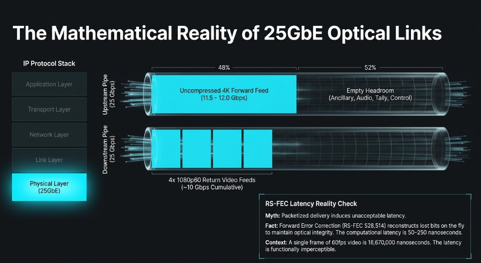
Reed-Solomon is a robust mathematical error-recovery algorithm that injects redundant parity data into the network stream, allowing the receiving SFP28 silicon to dynamically reconstruct lost or corrupted bits on the fly. (The Broadcast Knowledge) While RS-FEC is vital for maintaining an error-free transmission over fiber, it introduces a processing latency penalty at the network interface layer. (Medium) Extensive empirical testing of 25GbE network adapters indicates that the computational overhead of RS-FEC induces approximately 50 to 250 nanoseconds (ns) of latency compared to uncorrected 10GbE links. (Medium)
In the highly critical realm of live broadcast video, latency is fiercely scrutinized. (The Broadcast Bridge) However, when contextualized against the temporal realities of video production, a 50 ns latency impact is microscopically negligible. A single frame of 60 frames-per-second video persists for 16.67 milliseconds; therefore, the physical layer latency introduced by 25GbE FEC represents a fraction of a percent of a single frame. Overall system latency in a properly provisioned ST 2110 network-factoring in switch buffering, network traversal, and endpoint encapsulation-remains strictly sub-millisecond, competing directly with the near-zero latency characteristics of direct, point-to-point SDI hardware routing. (Packet Storm)
The Essence-Based Architecture of SMPTE ST 2110
The underlying philosophy of the SMPTE ST 2110 standard dictates that professional media must be completely decoupled from its legacy physical transport constraints. (ENENSYS Technologies) Prior to the ratification of ST 2110, the industry briefly experimented with SMPTE ST 2022-6, an early IP standard that operated on a strict encapsulation model. (RAVENNA Network) ST 2022-6 took the entirety of the baseband SDI payload-active video, horizontal and vertical blanking intervals, embedded multi-channel audio, and ancillary metadata-and wrapped it unaltered into a heavy IP datagram. (ENENSYS Technologies) While this allowed SDI signals to traverse Ethernet switches, it maintained the rigid inefficiencies of bundled baseband architecture. (ENENSYS Technologies) For instance, if an IP-based audio console required only the microphone feeds from a specific camera, the network was still forced to route the entire multi-gigabit ST 2022-6 video payload to the audio desk, drastically wasting network bandwidth and endpoint processing power.
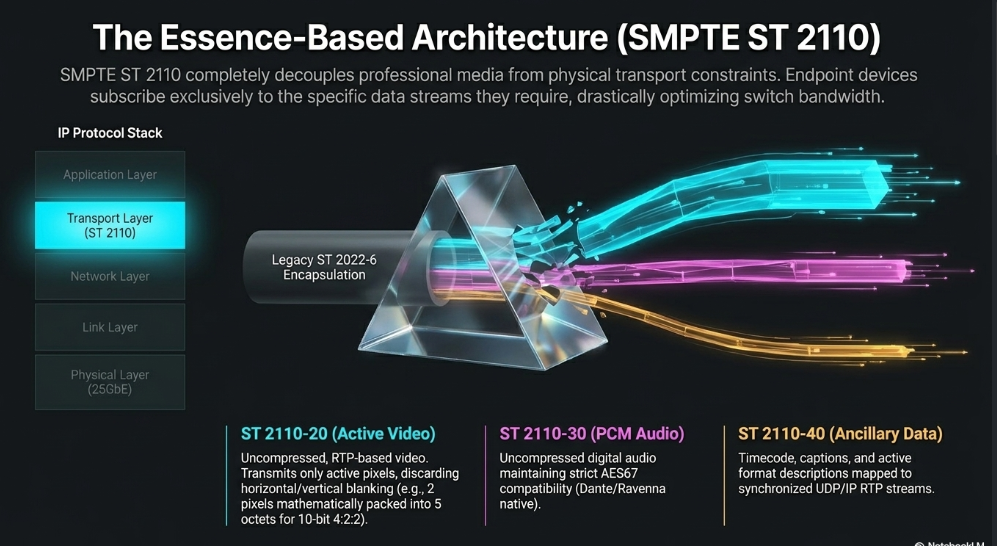
SMPTE ST 2110 entirely abandons encapsulation in favor of an "essence-based" transport methodology. (ENENSYS Technologies) Developed initially from the Video Services Forum (VSF) Technical Recommendation TR-03, the standard deconstructs the traditional composite broadcast signal into discrete, independent, self-contained IP streams known as essences. This granular separation allows endpoint devices on the 25GbE network to subscribe exclusively to the specific data streams they require, drastically optimizing network bandwidth utilization and enabling highly flexible, dynamic production workflows.
The SMPTE ST 2110 suite is partitioned into a modular family of technical documents, each defining the handling of a specific essence type:
SMPTE ST 2110-10 (System Timing and Definitions): This foundational layer dictates the underlying system timing model. It specifies how the network synchronizes devices and mandates the timestamping mechanisms required for Real-time Transport Protocol (RTP) packetization, ensuring that independently routed essences can be perfectly realigned by the receiving device.
SMPTE ST 2110-20 (Uncompressed Active Video): Specifies the real-time, RTP-based transport of uncompressed video essences over IP. Crucially, unlike SDI which transmits blanking intervals, ST 2110-20 transmits only the active picture pixels, yielding bandwidth efficiencies. It supports extreme scalability, facilitating standard definition, 4K, 8K, and up to 32K by 32K resolutions, varying color spaces (RGB, YCbCr), and HDR capabilities without requiring fundamental changes to the standard. (intoPIX)
SMPTE ST 2110-21 (Traffic Shaping and Delivery Timing): A critical component ensuring network stability, this standard governs the exact pacing and delivery timing of uncompressed video packets entering the network, preventing sender devices from overwhelming switch buffers.
SMPTE ST 2110-22 (Constant Bit-Rate Compressed Video): Allows the transport of lightly compressed video payloads, primarily utilized with ultra-low latency JPEG XS codecs, allowing 4K and 8K signals to traverse bandwidth-constrained WANs or 10GbE legacy links.
SMPTE ST 2110-30 (PCM Digital Audio): Handles the transport of uncompressed Pulse Code Modulation (PCM) audio streams, maintaining strict compatibility with the pre-existing AES67 Audio over IP standard, allowing seamless integration with Dante and Ravenna audio ecosystems. (SMPTE)
SMPTE ST 2110-31 (AES3 Transparent Transport): Provides a mechanism for the real-time, RTP-based transport of AES3 signals, accommodating non-PCM audio formats and legacy digital audio payloads. (SMPTE)
SMPTE ST 2110-40 (Ancillary Data): Maps legacy SDI ancillary data packets (such as timecode, closed captions, and active format descriptions defined in SMPTE ST 291-1) into synchronized UDP/IP RTP streams.
SMPTE ST 2110-41 (Fast Metadata Framework): Defines a highly flexible RTP payload framework for transporting generic data items tightly time-associated with video or audio essences. (SMPTE)
To transport an uncompressed 4K video frame, the ST 2110-20 specification groups individual pixels into specific byte alignments known as "pgroups" (pixel groups) depending on the color depth and sampling format. (AIMS Alliance) For a standard 10-bit 4:2:2 broadcast signal, two pixels are mathematically packed into five octets. (AIMS Alliance) These pgroups are appended with an RTP payload header, inserted into an RTP packet featuring a 32-bit sequence number, wrapped into a User Datagram Protocol (UDP) packet, attached to an IP packet header, and finally encapsulated into an Ethernet MAC frame for transmission across the 25GbE optical switch fabric. (AIMS Alliance) The maximum UDP datagram size is typically 1460 octets, though extended datagrams up to 8960 octets are permitted for optimized switch processing. (AIMS Alliance)
Mathematical Realities of 4K Video Over 25GbE Bidirectional Links
The architecture of ST 2110 operating over 25GbE fundamentally resolves the directional and physical capacity limitations of legacy SDI. A single 25 Gigabit Ethernet fiber interface operates in full-duplex mode, providing 25 Gbps of downstream bandwidth and 25 Gbps of upstream bandwidth concurrently. (AJA) This massive bidirectional capacity enables the consolidation of multiple discrete baseband cables into a single optical strand serving the camera chain. (AWS)
Table 2: Bandwidth consumption comparison demonstrating the data efficiency of the ST 2110-20 active-video essence model versus the legacy ST 2022-6 full-raster encapsulation model. (RAVENNA Network)
To fully illustrate the capability of a 25GbE link, one must analyze the mathematical payload of a modern 4K live broadcast environment. A primary uncompressed 4K forward video stream (3840x2160 pixels, 59.94 fps, 10-bit color, 4:2:2 sampling) consumes approximately 11.5 to 12.0 Gbps of IP network payload when factoring in all necessary RTP, UDP, and Ethernet frame overhead. This single stream entirely saturates a legacy 10GbE network link, proving why 25GbE is the foundational requirement for modern high-tier production. (Packet Storm)
However, on a 25GbE optical link, this 12 Gbps transmission consumes less than half of the available transmit capacity. This vast remaining headroom allows the same optical fiber to simultaneously carry the high-quality embedded microphone audio utilizing ST 2110-30 (which typically consumes mere megabits of bandwidth), along with ancillary metadata via ST 2110-40. (SMPTE)
Simultaneously, the full-duplex nature of the 25GbE SFP28 interface allows massive payloads to travel in the reverse direction, from the network core back to the camera head. (AJA) This is critically utilized for return video monitoring. A broadcast camera operator requires visual access to the program feed, teleprompter outputs, and auxiliary camera angles to maintain context during a live production. (Sony Pro) The 25 Gbps receiving pipeline on the camera's network interface can comfortably accept either a full uncompressed 4K return video stream (consuming another 12 Gbps), or, more commonly, up to four distinct uncompressed 1080p60 HD return video feeds (consuming roughly 2.5 Gbps each, or 10 Gbps cumulatively).
This bidirectional consolidation eliminates the need for separate 12G-SDI cables for forward video, distinct 3G-SDI cables for return video, dedicated serial cables for camera control, and analog copper lines for tally and intercom. (Key Code Media) Devices like the AJA IP25-R IP video converter and high-end Sony HDCU-5500 Camera Control Units leverage this exact paradigm, utilizing dual SFP28 cages to handle bidirectional ST 2110 essence processing directly at the edge of the network. (AJA)
Network Routing Dynamics and IP Multicast Distribution
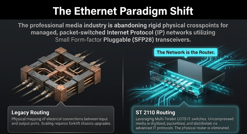
The migration from physical baseband routing to packet-switched network infrastructure represents a fundamental operational shift. In legacy environments, signal distribution is rigidly dictated by hardware. A centralized SDI crosspoint router physically maps the electrical connection between an input port (a camera) and an output port (a monitor). Scaling these systems is notoriously difficult; once an SDI router reaches its maximum physical chassis capacity (e.g., 1152 inputs by 1152 outputs), expansion requires a massively expensive forklift upgrade. (Key Code Media)
Under the SMPTE ST 2110 paradigm, the physical router is entirely eliminated; "the network is the router". (Reddit) Signal routing is orchestrated exclusively via standard IT networking protocols, fundamentally relying upon IP Multicast architecture. (Diversified)
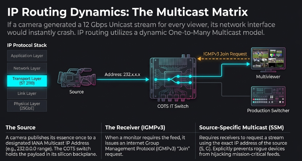
If a 25GbE camera generates a 12 Gbps ST 2110-20 4K video essence, it does not send that data directly to the IP address of a specific viewing monitor (a Unicast transmission). (Advanced Systems Group) If multiple destinations required the signal, a Unicast model would force the camera to duplicate the 12 Gbps stream for every recipient, instantly overwhelming the camera's network interface and causing catastrophic packet loss. (Advanced Systems Group)
Instead, the camera transmits a single, continuous stream to a designated Multicast IP address. (Advanced Systems Group) The Internet Assigned Numbers Authority (IANA) designates the IPv4 address range of 224.0.0.0 through 239.255.255.255 strictly for multicast traffic. (Arista) When the high-capacity IT switch receives this single media stream, it holds the data within its silicon backplane but does not autonomously flood the network with the heavy video packets. (Arista)
Signal distribution is actively managed by endpoint receivers utilizing the Internet Group Management Protocol version 3 (IGMPv3). When a production switcher or a multiviewer needs to ingest the camera feed, the endpoint transmits an IGMPv3 "Join" message to the network switch, formally requesting access to the specific multicast group address. (Advanced Systems Group) The COTS switch then dynamically duplicates the data packets within its high-speed backplane and routes the stream exclusively to the port where the request originated. (Advanced Systems Group) The "one-to-many" efficiency of multicast transmission means the originating camera is entirely decoupled from the routing logic; it simply publishes its essence once, while the core IT switches handle the massive parallel data replication, leveraging the multi-terabit switching capacities characteristic of modern data center hardware. (Diversified)
Advanced broadcast implementations heavily recommend the use of Source-Specific Multicast (SSM), operating within the 232.0.0.0 to 232.255.255.255 address block. (Arista) While standard IGMP allows a receiver to join any data stream matching a group address (G), SSM requires the receiver to request a stream utilizing both the multicast group address and the precise IP address of the source device (S, G). (Arista) This explicitly prevents rogue devices from hijacking a multicast feed or overlapping IP assignments from corrupting a mission-critical broadcast signal, ensuring deterministic and secure signal routing. (Arista)
Timing, Synchronization, and Traffic Shaping
Because ST 2110 fundamentally shatters the broadcast signal into independent essence streams-video, audio, and metadata-that traverse the network asynchronously via unique multicast routing paths, precise realignment at the destination is critical to prevent lip-sync errors and dropped frames. In SDI workflows, synchronization was centralized via a physical analog genlock signal (such as black burst or tri-level sync) distributed via dedicated coaxial cables to every piece of hardware in the facility. In the ST 2110 ecosystem, hardware genlock is completely deprecated in favor of the Precision Time Protocol (PTP), specifically the IEEE 1588-2008 standard profiled for broadcasting as SMPTE ST 2059-2. (SMPTE)
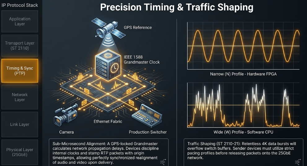
PTP operates entirely in-band across the 25GbE data network. A highly accurate Grandmaster clock, generally locked to a global positioning system (GPS) atomic reference, continuously exchanges precision timestamp messages with all participating network edge devices. This mathematically calculates network propagation delays and allows every camera, CCU, and vision mixer to discipline its internal hardware clock to match the Grandmaster with sub-microsecond accuracy. (Packet Storm)
Under SMPTE ST 2110-10, every media clock on the network must maintain an offset of zero relative to the epoch, facilitating rapid recovery from signal loss or hardware reboots. (AIMS Alliance) As a camera generates uncompressed ST 2110-20 video frames and ST 2110-30 audio samples, it brands all corresponding RTP packets with identical origin timestamps derived from the PTP reference. When an endpoint receiver aggregates the disparate multicast streams, its silicon buffer cross-references the RTP timestamps, perfectly realigning the active video with its corresponding PCM audio and metadata before playout, ensuring synchronous presentation regardless of varying network transit delays. (SMPTE)
Network Stability via Sender Traffic Shaping (ST 2110-21)
While PTP governs timing, SMPTE ST 2110-21 governs the volumetric flow of data to preserve network integrity. A raw uncompressed video stream produces a relentless cascade of data. If a sender emits packets in rapid, uncontrolled, dense bursts, it will instantly overflow the queuing buffers within the commercial IT switch, resulting in catastrophic packet drop and visual macroblocking. (AWS)
ST 2110-21 dictates strict traffic shaping models that 25GbE sender devices must implement prior to releasing packets onto the network. These profiles are classified primarily into Narrow (N), Narrow Linear (NL), and Wide (W) designations. (intoPIX) Narrow senders are highly disciplined hardware devices (such as a hardware CCU or high-end FPGA edge gateway) that output IP packets with precise mathematical pacing, mirroring the original SDI baseband raster timing exactly. Wide senders allow for greater jitter and packet variability, a profile frequently necessary for software-based media servers and graphics generators where CPU processing cycles inherently fluctuate. (Brompton Technology) Designing a reliable 25GbE core fabric requires engineers to actively model the switch buffer depth to accommodate the specific ratio of Narrow to Wide senders operating within the facility. (Brompton Technology)
The Control Plane: AMWA NMOS Discovery and Connection Management
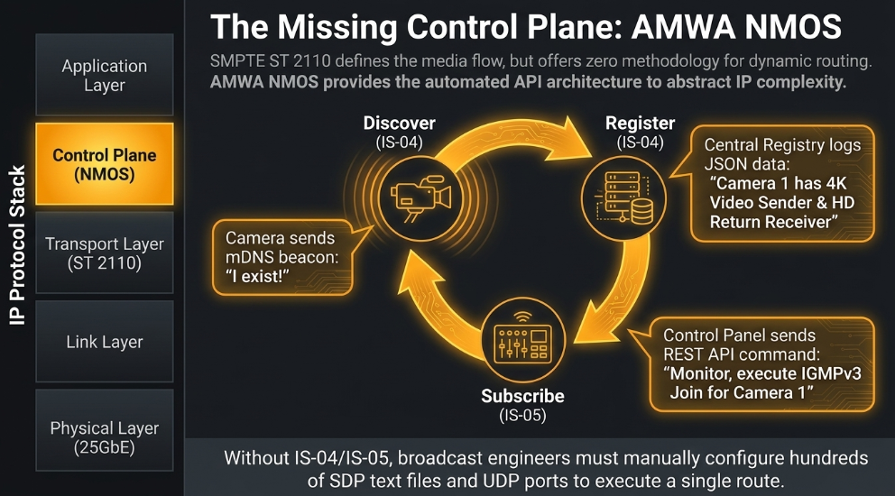
While the SMPTE ST 2110 suite brilliantly engineers the data plane-dictating exactly how uncompressed media flows across an Ethernet network-it completely omits the control plane. (Murat Demirci) The ST 2110 documentation offers zero methodology for how devices discover each other, how to orchestrate IGMPv3 routing dynamically, or how to manage complex telemetry. (Murat Demirci) If a facility implemented ST 2110 without an overarching control structure, broadcast engineers would be forced to manually configure hundreds of endpoint web interfaces, inputting raw multicast IP addresses, UDP port numbers, and Session Description Protocol (SDP) text files to establish a simple signal route. This manual configuration methodology is entirely untenable for live, dynamic multi-camera broadcasting. (Murat Demirci)
To rectify this monumental gap, the industry universally adopted the Advanced Media Workflow Association (AMWA) Networked Media Open Specifications (NMOS). NMOS is an open-source, free-to-use family of specifications that implements a standardized, vendor-agnostic control plane utilizing modern IT-centric RESTful APIs, hierarchical JSON data structures, and continuous network monitoring to abstract the complexity of IP routing. (SMPTE)
Automating the IP Matrix: IS-04 and IS-05
The fundamental pillars of the NMOS framework are IS-04 (Discovery and Registration) and IS-05 (Device Connection Management). (Murat Demirci) When a modern, NMOS-enabled 25GbE broadcast camera or CCU is connected to the network, it does not require manual IP assignment or routing logic. (Murat Demirci) Through the implementation of IS-04, the device automatically locates the central network Registry utilizing Multicast DNS (mDNS) or Unicast DNS Service Discovery (DNS-SD) protocols. (Murat Demirci) The camera subsequently registers its existence, its manufacturer details, its physical capabilities, and a full catalog of its available Senders (e.g., ST 2110-20 4K output, ST 2110-30 audio output) and Receivers (e.g., ST 2110-20 return video inputs). (Murat Demirci) A central broadcast controller queries this active registry, presenting human operators with a unified, real-time inventory of all networked hardware that feels identical to operating a legacy baseband router interface. (Murat Demirci)
Routing execution is subsequently handled by NMOS IS-05. (Murat Demirci) When an operator attempts to route "Camera 1" to "Monitor A," the broadcast controller issues a standard REST API command directly to the monitor's IS-05 management interface. (Murat Demirci) The API payload contains the exact SDP parameters required to consume the camera's essence flow. (Murat Demirci) The monitor instantaneously processes the JSON instruction and autonomously generates the corresponding IGMPv3 Join command directed at the core IT switch, completely abstracting the complex underlying network topology away from the broadcast operator. (Murat Demirci)
Additional NMOS specifications continually refine the environment: IS-08 provides logical audio channel mapping and bundling within devices; IS-09 manages global system parameters ensuring consistent PTP configurations; and IS-10 introduces OAuth2 authorization security models and TLS certificate handling to prevent unauthorized tampering of the media routing fabric. (Murat Demirci)
Modernizing Telemetry: Tally Lights and Camera Control over IP
In legacy SDI architectures, the auxiliary data necessary for operating a camera chain-specifically tally light signaling and camera shading parameters-relied upon parallel, proprietary analog systems. (Panasonic Connect) The SMPTE ST 2110 and NMOS integration comprehensively digitizes and standardizes these telemetry functions, transmitting them directly over the 25GbE optical fiber. (Panasonic Connect)
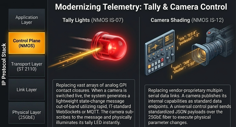
The Evolution of Tally Signaling: ST 2110-40 versus NMOS IS-07 A non-negotiable requirement in live multicamera production is accurate tally light signaling-the illumination of a red indicator on the camera body notifying the talent and the operator that their specific camera angle is currently "on air" and live to the public. (Panasonic Connect) Historically, this data was relayed from the vision mixer to the camera via rudimentary physical contact closures, known as General Purpose Interfaces (GPIs), requiring vast arrays of dedicated low-voltage copper wiring completely divorced from the video signal. (AMWA)
Within an IP video environment, tally integration typically follows one of two methodologies:
In-Band Embedding via SMPTE ST 2110-40: Tally commands can be treated as standard broadcast metadata and embedded directly into the IP network stream as Ancillary (ANC) data using ST 2110-40. Because ST 2110-40 is strictly tethered to the PTP timing model alongside the uncompressed video, the tally signal remains frame-accurately synchronized with the picture. However, this method requires the camera's edge processing silicon to continuously ingest and parse heavy, high-bandwidth multicast RTP packet streams simply to extract a few bytes of binary tally logic, creating unnecessary computational overhead. (The Broadcast Bridge)
Out-of-Band State Messaging via AMWA NMOS IS-07: The modern, highly preferred industry approach is the implementation of AMWA NMOS IS-07 (Event & Tally). (Murat Demirci) IS-07 completely abandons video-bound ancillary data protocols in favor of an IT-native mechanism designed explicitly to carry time-sensitive, state-based information. (AMWA) When a vision mixer switches a camera to the program bus, the central control system generates a lightweight IS-07 state change message. (AMWA) Instead of utilizing heavy UDP multicast streams, IS-07 transmits these messages out-of-band utilizing rapid, IT-standard WebSockets or Message Queuing Telemetry Transport (MQTT) protocols. (AMWA) The camera, which has subscribed to this specific IS-07 messaging flow via IS-05 connection management, receives the WebSocket payload almost instantaneously and triggers its physical tally LED. (AMWA) Because IS-07 is an open standard, it provides an exact, network-agnostic software equivalent to physical GPI functionality, permanently eliminating the industry's reliance on vendor-proprietary, closed-ecosystem tally relay boxes. (AMWA)
Standardizing Camera Shading via NMOS IS-12 Camera control presents an equally complex challenge. Remote shading, iris adjustment, black level calibration, and complex colorimetry parameters have historically been managed by highly proprietary serial data protocols. (Panasonic Connect) A Sony camera required a Sony remote control panel (RCP) communicating over a proprietary data bus, completely incompatible with equipment from Panasonic or Grass Valley. (Panasonic Connect)
To unify telemetry over the 25GbE IP fabric, the AMWA initiative developed NMOS IS-12 (Control Protocol). (VSF) IS-12 establishes a universal, vendor-agnostic framework governing device control and continuous monitoring. (VSF) The specification dictates a standardized methodological approach for exposing the internal "control models" of a device. (AMWA) Under IS-12, a broadcast camera publishes its controllable parameters (such as optical iris opening or master pedestal level) as accessible data endpoints. (AMWA) A universal broadcast control panel can subsequently interact with these endpoints, transmitting standardized JSON payloads over the network to execute physical parameter changes. (VSF) The IS-12 control traffic travels across the 25GbE optical link alongside the heavy ST 2110 video and audio essences, consolidating comprehensive machine control onto the unified IP transport layer without requiring any proprietary translation gateways. (VSF)
Table 3: The structural evolution of broadcast telemetry, contrasting legacy hardware protocols with software-defined NMOS IT standards. (Murat Demirci)
Fault Tolerance and System Resilience: SMPTE ST 2022-7
A persistent critique regarding the transition from monolithic SDI hardware to software-defined IP networks is the perceived vulnerability of packetized data delivery. (Key Code Media) A damaged coaxial cable constitutes a localized, single-point failure; conversely, a misconfigured core network switch, an STP routing loop, or severe network congestion can cascade into a complete, facility-wide transmission collapse. (Key Code Media)
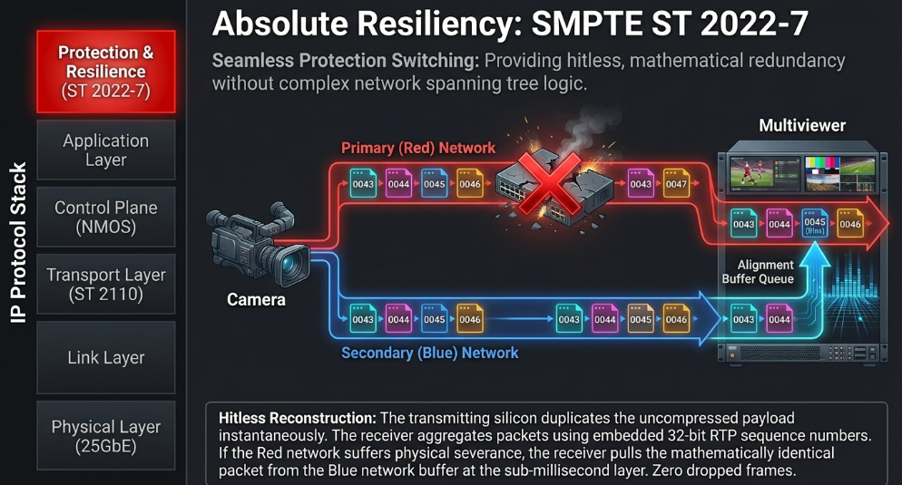
To ensure the zero-tolerance failure criteria demanded by tier-one live broadcasting (such as global sporting events), the ST 2110 ecosystem strictly integrates SMPTE ST 2022-7, formally defined as "Seamless Protection Switching". (SMPTE)
ST 2022-7 provides absolute mathematical redundancy without requiring complex network spanning tree logic. (SMPTE) The standard dictates an architecture where all participating edge devices possess two physically discrete, totally isolated network interface ports. (AJA) These are universally referred to within the industry as the Primary (Red) network and the Secondary (Blue) network. (Brompton Technology) The Red and Blue networks utilize distinct switch chassis, independent power supplies, and discrete optical fiber paths, ensuring zero physical overlap. (Brompton Technology)
When an IP-enabled camera or CCU originates an uncompressed 4K video stream, its internal silicon duplicates the ST 2110-20 packet payload instantaneously. (Brompton Technology) It transmits the primary copy out of the Red SFP28 transceiver and an exact, identical duplicate out of the Blue SFP28 transceiver. (Brompton Technology) Both packet streams traverse their completely isolated respective network fabrics. (Brompton Technology)
At the destination, the receiving device (such as a vision mixer, multiviewer, or an edge gateway like the AJA IP25-R) is similarly connected to both the Red and Blue switch fabrics. (AJA) As packets arrive from both networks, the receiver's silicon rapidly aggregates them into a highly disciplined alignment buffer, utilizing the embedded 32-bit RTP sequence numbers to cross-reference and align the dual streams. (AIMS Alliance)
If the Red network is operating flawlessly, the receiver reconstructs the video frame utilizing the primary packets. (Brompton Technology) However, if a switch fails, an optical fiber is severed, or micro-burst congestion induces packet loss on the Red network, the receiving silicon detects the missing sequence number and instantaneously pulls the identical replacement packet from the Blue network's buffer. (Brompton Technology) Because the redundant packets are mathematically identical and inherently synchronized via PTP, the reconstruction of the uncompressed video frame occurs continuously at the sub-millisecond network layer. (Brompton Technology) The video output never registers a dropped frame, visual artifact, or stutter; the infrastructure failure is entirely invisible to the viewing audience. (Plura) This "hitless" redundancy mechanism, operating relentlessly over dual 25GbE links, yields an operational reliability that far surpasses the capabilities of singular baseband SDI routing structures. (Brompton Technology)
Hardware Abstraction and Real-World Deployments
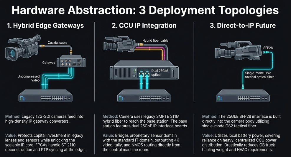
Translating the dense theoretical specifications of ST 2110, NMOS, and 25GbE optical networking into functional field deployments reveals a spectrum of integration strategies, heavily dependent on legacy equipment lifecycle management and operational scale. The integration of complex camera chains into this IP fabric generally manifests in three primary architectural topologies: Edge Gateway adaptation, CCU-based integration, and Direct-to-IP camera heads. (Sony Pro)
The Hybrid Edge Gateway Strategy For the vast majority of broadcasting facilities, instantly depreciating an entire fleet of 12G-SDI cameras and switchers to purchase native IP hardware is economically impossible. (Key Code Media) Consequently, facilities adopt a hybrid migration path. The core routing infrastructure is upgraded to COTS IT switches running ST 2110, while the facility edge utilizes high-density gateway converters. Devices such as the AJA IP25-R or the Blackmagic Design 2110 IP Converter act as the translation layer. (AJA) Legacy baseband cameras output standard SDI into the gateway device. (AJA) The gateway's FPGA silicon ingests the SDI raster, perfectly deconstructs it into separate ST 2110-20 video, ST 2110-30 audio, and ST 2110-40 ancillary streams, synchronizes the output against the facility's PTP Grandmaster, and transmits the uncompressed packets over dual 25GbE SFP28 cages utilizing ST 2022-7 hitless redundancy. (AJA) In the reverse path, the gateway subscribes to return video multicast streams via IGMPv3, encapsulates them back into SDI, and sends them to the camera. (AJA) This hybrid strategy protects massive capital investments in legacy optical blocks and lenses while immediately unlocking the limitless routing scalability of the IP core fabric. (Diversified)
Camera Control Unit (CCU) IP Integration For high-end, multi-camera live productions utilizing SMPTE 311M hybrid fiber ecosystems, manufacturers have integrated the ST 2110 gateway logic directly into the base station. (Panasonic Connect) The Sony HDCU-5500 Camera Control Unit exemplifies this integration. (Sony Pro) The HDC-5500 camera head on the studio floor remains entirely unaware of the IP network; it communicates with the HDCU-5500 utilizing the proprietary, multiplexed optical data stream and high-voltage power lines inherent to the traditional SMPTE 311M cable. (Sony Pro)
However, the HDCU-5500 base station residing in the centralized machine room entirely eschews baseband SDI outputs. (Sony Pro) Equipped with the HKCU-SFP50 IP interface option board, the CCU bridges the proprietary camera domain with the standardized IT domain. (Sony Pro) The base station processes the proprietary sensor telemetry and dynamically generates the standards-compliant ST 2110 essence streams. (Sony Pro) Over its dual 25GbE optical interfaces, the CCU can simultaneously transmit an uncompressed 4K forward feed, multiple 1080p HD feeds, while concurrently subscribing to up to three distinct HD return video multicast streams from the network switch to feed back to the operator. (Sony Pro) Furthermore, tally and remote shading control are native, directly processing NMOS IS-04 and IS-05 API requests, allowing universal control panels via Cerebrum or VSM to manage the camera without legacy serial data cabling. (Sony Pro)
The Direct-to-IP Future The ultimate architectural evolution of the ST 2110 ecosystem bypasses the base station completely, moving the 25GbE SFP28 interface directly into the camera chassis. (Panasonic Connect) Next-generation broadcast cameras encapsulate uncompressed sensor data directly into ST 2110 RTP packets internally. (Panasonic Connect) By plugging a standard single-mode tactical fiber directly into the camera body, the camera natively registers to the NMOS IS-04 directory, synchronizes its sensor scanning to the PTP network clock, subscribes to IS-07 WebSocket tally data, and communicates directly with the core IT leaf switch. (Panasonic Connect)
This methodology profoundly alters outside broadcast logistics. Because standard tactical optical fiber (such as OS2) contains no heavy copper conductors, it cannot transmit electrical power. (Panasonic Connect) In direct-to-IP deployments, the camera must be powered locally via high-capacity battery plates or localized AC power supplies. (Reddit) By severing the reliance on centralized CCU power distribution, facilities can eliminate massive equipment racks from OB trucks, drastically reducing hauling weight, air conditioning requirements, and complex cable management, fundamentally altering the economics of remote distributed production. (Key Code Media)
This same native-IP hardware abstraction extends beyond cameras into endpoint display technology. Large-scale LED processing units, such as the NovaStar MX6000 Pro or the Disguise IPvfc card, now feature direct 25GbE SFP28 ingest ports. Instead of requiring complex HDMI or 12G-SDI routing matrices, these display controllers utilize IGMPv3 to directly subscribe to uncompressed 4K ST 2110-20 multicast streams straight from the IP switch, streamlining the signal path for massive in-stadium displays and virtual production volumes. Similarly, cloud integrations utilizing platforms like AWS Elemental Live natively ingest ST 2110 essences and NMOS control API traffic directly from the 25GbE physical interfaces, seamlessly bridging the on-premise uncompressed IP environment with global cloud distribution networks without relying on intermediate baseband decoding steps. (AWS)
Strategic Implications and Operational Outlook
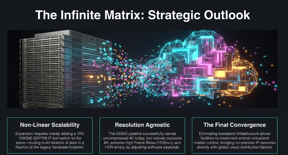
The transition from a 12G-SDI physical routing architecture to an SMPTE ST 2110 workflow operating over 25GbE fiber requires unprecedented shifts in technical strategy, capital expenditure, and operational philosophy. (Key Code Media) The primary, overwhelming advantage of the ST 2110 architecture is unparalleled, non-linear scalability. Traditional SDI routers hit strict hardware limits, forcing complete infrastructure replacement to expand port counts. Because ST 2110 relies upon standard IP networking, expanding a facility merely requires the addition of a new high-speed COTS leaf switch connected to the spine fabric. (Packet Storm) A standard 1 Rack Unit (1RU) IT switch equipped with dense 100GbE QSFP28 ports can route multiple terabits of data per second-drastically exceeding the capacity of the largest monolithic SDI routers while consuming a fraction of the physical rack space and thermal footprint. (Diversified)
Furthermore, the ST 2110 standard is intentionally resolution and format-agnostic. (RAVENNA Network) A single 25GbE optical link successfully carries an uncompressed 4K stream today, but the exact same underlying Ethernet standard seamlessly supports 8K video, HDR, extreme High Frame Rates (120fps+), and custom non-standard aspect ratios merely by adjusting the software payload encapsulation and SDP timing files. This provides absolute, long-term future-proofing against shifting television standards, allowing broadcasters to ride the relentless innovation curve of the multi-trillion-dollar enterprise IT industry rather than funding bespoke, dead-end baseband hardware research. WTTG/WDCA, the first local television facility built entirely from the ground up on ST 2110 technology, demonstrated that by eliminating massive SDI infrastructure, the facility could implement entirely virtualized master control switching and graphics processing layers natively within the IP domain. (SMPTE)
Despite these massive long-term architectural benefits, the transition introduces severe short-term operational friction. (Packet Storm) Legacy broadcast engineers, historically accustomed to tracing a physical video signal down a coaxial cable utilizing a waveform monitor, must rapidly and comprehensively upskill into IT network architecture. Debugging a modern ST 2110 system requires an intimate understanding of IGMPv3 multicast groups, PTP hierarchy optimization, NMOS API JSON validation, and deep Wireshark packet analysis. Because "the network is the router," a simple misconfiguration of Quality of Service (QoS) queues or an IP address overlap can cascade into a catastrophic failure across the entire production environment, a risk profile that does not exist in point-to-point SDI configurations.
Conclusion
The architectural evolution from the Serial Digital Interface (SDI) to the SMPTE ST 2110 suite of standards over managed IP networks represents the definitive technological leap in modern broadcast engineering. By intentionally discarding the rigid, hardware-bound limitations of bundled, point-to-point baseband connections, ST 2110 establishes a highly modular, essence-based data plane where uncompressed 4K video, audio, and metadata are independently routed with mathematical precision utilizing advanced IGMPv3 multicast structures.
The integration of 25 Gigabit Ethernet optical networking provides the essential, high-capacity physical layer necessary to realize this standard's full potential without resorting to visually compromising compression. The 25 Gbps threshold is vital; it effortlessly accommodates the simultaneous transmission of a demanding ~12 Gbps uncompressed 4K ST 2110-20 forward video stream, alongside multiple high-definition return feeds, bidirectional PTP timing signals, and sub-millisecond audio payloads. This bidirectional consolidation effectively replaces massive looms of heavy, inflexible copper cabling with a single, highly resilient optical fiber strand, protected from packet loss by inherent RS-FEC algorithms that introduce functionally imperceptible latency. (AWS)
However, the raw uncompressed power of the ST 2110 data plane is operationally viable only when governed by robust, standardized control methodologies. (Murat Demirci) The AMWA NMOS suite of specifications is the critical software bridge between theoretical IP routing capability and practical, day-to-day broadcast execution. By aggressively substituting primitive hardware contact closures with modern, WebSocket-driven architectures via IS-07 for tally data, automating dynamic network discovery through IS-04, and standardizing complex camera shading telemetry utilizing IS-12 JSON payloads, NMOS transforms disparate broadcast hardware into a unified, secure, IT-centric ecosystem. (Murat Demirci)
As the broadcast industry rapidly approaches a reality dominated by ultra-high-definition, multi-platform, and decentralized remote production, legacy SDI architectures will continue to face insurmountable physical bottlenecks. SMPTE ST 2110, secured by the hitless redundancy of ST 2022-7 and powered by the 25GbE physical layer, provides the definitive, infinitely scalable framework required to drive global broadcast facilities dynamically, economically, and securely into the next era of media production.