Introduction to In-Camera Visual Effects Infrastructures
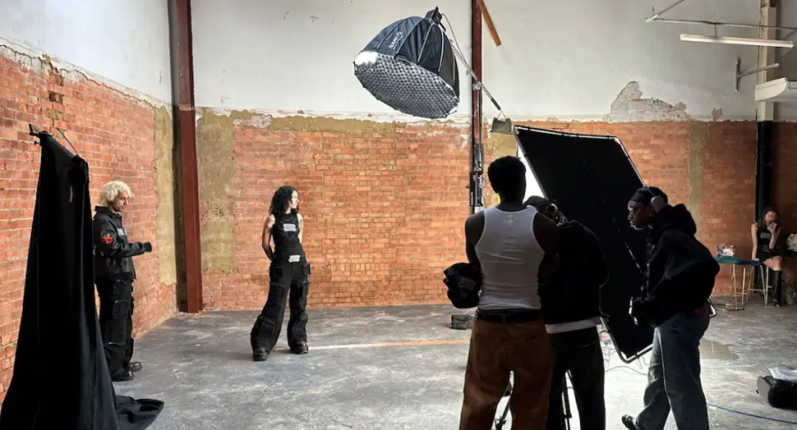
The transition from traditional post-production compositing to real-time, In-Camera Visual Effects (ICVFX) has profoundly redefined the technical paradigms of cinematic and broadcast production. By leveraging large-scale light-emitting diode (LED) volumes, productions are able to replace chroma-key environments with emissive, real-time rendered virtual sets that provide authentic interactive lighting, physically accurate reflections, and immediate on-set visualization. The ecological and financial advantages are equally substantial; smaller "micro stages" significantly reduce power consumption, minimize crew travel expenses, and lower physical set construction costs, all while utilizing technologies like Ultimatte and disguise to execute live virtual set extensions beyond the physical boundaries of the screen Frame.io Insider.
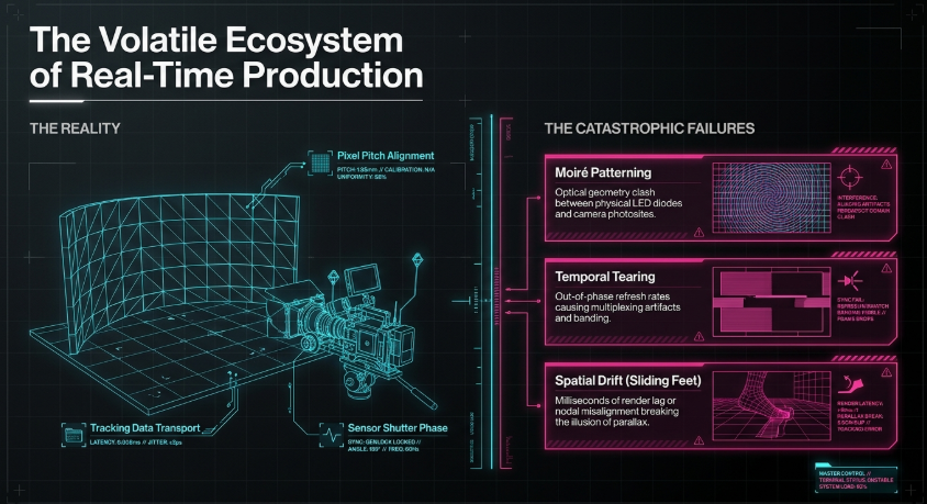
However, the intersection of physical cinematography with real-time digital rendering introduces a matrix of extraordinary technical challenges. An LED volume operates as a highly volatile ecosystem where spatial positioning, temporal synchronization, and optical physics must align with microsecond and sub-millimeter precision. The physical interactions of talent and optical recording occur in real-time, whereas the virtual ecosystem must capture, transport, and process vast amounts of data, inevitably introducing computational delay. If any element of this pipeline-ranging from the tracking servers to the rendering engine and the LED processor-falls out of synchronization, the illusion of reality collapses immediately ROE Visual.
When these intricate systems misalign, they produce catastrophic visual artifacts. The most prevalent of these is the moiré effect, an optical interference pattern caused by the geometric clash between the physical LED pixel grid and the camera sensor's photosite array Panasonic. Furthermore, spatial latency manifests as a jarring disconnect-often perceived as "swimming" or "sliding feet"-where the virtual background fails to update synchronously with the physical camera's movement. Tearing, banding, and multiplexing artifacts further degrade the image when the camera's shutter is out of phase with the LED processor's refresh cycle Panasonic.
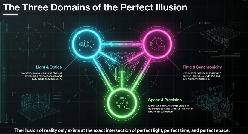
This report delivers an exhaustive technical analysis of the physical, electronic, and software parameters required to eliminate moiré patterns and visual latency within ICVFX environments. It explores exact pixel pitch requirements through complex optical mathematics, evaluates advanced synchronization frameworks including SMPTE ST 2059 and sub-framing protocols (GhostFrame and Brompton Frame Remapping), and dissects the hardware pipelines of leading camera-tracking architectures like Mo-Sys StarTracker and OptiTrack CinePuck. Additionally, the analysis extends into Unreal Engine 5.4's nDisplay topology and nodal offset calibration, providing a comprehensive framework for achieving zero-latency, artifact-free virtual production.
The Optical Physics of Moiré and Pixel Pitch Requirements
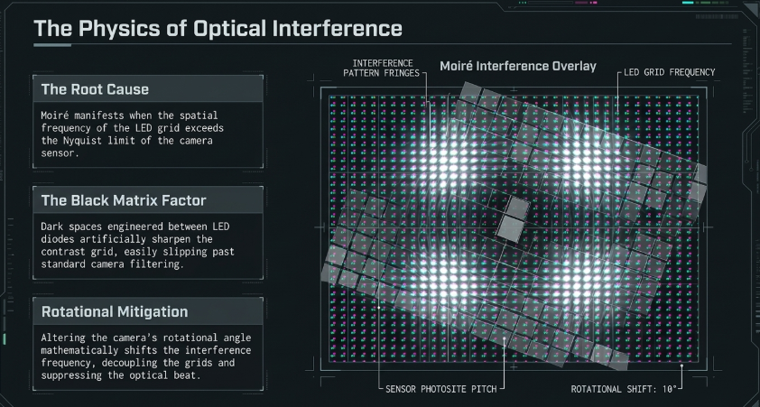
Moiré is an optical interference phenomenon that manifests when two high-frequency, regular geometrical patterns are superimposed at differing scales, angles, or spatial frequencies Panasonic. In the context of an LED volume, these two interfering grids are the physical arrangement of individual light-emitting diodes on the display panel and the microscopic grid of photosites on the camera's image sensor.
The manifestation of moiré is rarely a defect of the screen itself; rather, it is a fundamental camera sampling issue occurring when the spatial frequency of the LED grid exceeds the Nyquist limit of the camera's sensor Panasonic. Modern LED panels are constructed with a "black matrix"-the non-emissive dark space between individual LED diodes-which is engineered to improve contrast and black levels Panasonic. However, this black matrix effectively doubles the pattern frequency of the display, delivering an artificially sharp contrast grid that easily slips past standard camera filtering mechanisms Panasonic. When the camera "samples" this layout, the interference translates into undulating rainbow bands, ripples, or shifting lines that destroy the integrity of the captured image. Because LED walls are emissive and not continuous flat colors, balancing the optics and sensors requires matching the Nyquist frequency of the sensor, calculated as $1/(2\times pixel~pitch)$, with the optical cutoff frequency of the lens Panasonic.
Mathematical Frameworks for Viewing Distance and Spatial Frequency
To prevent moiré without relying on aggressive optical diffusion, the physical distance between the camera sensor and the LED wall must be calculated so that the individual LED pixels merge into a continuous color field, falling below the sensor's resolving capability. The foundational metric dictating this relationship is "Pixel Pitch," defined as the measurement in millimeters of the exact space between the centers of two adjacent LED packages Planar.
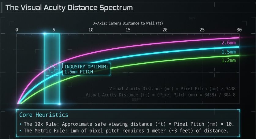
The industry utilizes several mathematical models to determine the optimal relationship between pixel pitch and camera distance. The most basic heuristic is the "10x Rule," a shorthand method stipulating that the approximate safe viewing distance in feet is equal to the pixel pitch in millimeters multiplied by 10 Planar. For example, a 2.5mm pixel pitch screen requires a viewing distance of approximately 25 feet Planar. A secondary industry approximation dictates that for every 1 millimeter of pixel pitch, the camera should be at least 1 meter (or approximately 3 feet) away to perceive a seamless image without obvious grid separation Christie Digital.
However, high-end cinematic applications require far more rigorous calculations. The absolute threshold is defined as the Visual Acuity Distance (or "Retina Distance"), which represents the formulated calculation of the distance at which a high-resolution optical system can no longer distinguish individual pixels Planar. This is calculated using the scale factor of 1 arc minute: Visual Acuity Distance (mm) = Pixel Pitch (mm) x 3438.
Hardware-Level Display Architectures and Encapsulation
When spatial constraints within a studio prevent the camera from maintaining the calculated Visual Acuity Distance, physical interventions at the display level are required to suppress the high-frequency components of the LED grid. The manufacturing architecture of the LED modules plays a massive role in moiré susceptibility.
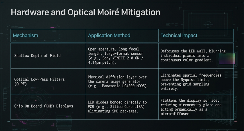
Traditional LED displays are manufactured using Surface Mount Device (SMD) architectures, where individual LED diodes are soldered onto a printed circuit board (PCB). SMDs feature exposed lenses and multiple reflective encapsulation interfaces, creating microcavity effects and glare that act as distinct, sharp point sources of light, thereby exacerbating moiré and off-axis color shifts. To combat this, manufacturers like Silicon Core have developed Chip-on-Board (COB) technologies, specifically the LED In Silicon Array (LISA) platform SiliconCore. By directly bonding the light-emitting diodes to the PCB and removing the traditional SMD packaging, COB displays present a highly uniform, mechanically rigid surface SiliconCore. This flat encapsulation reduces internal reflections and acts organically as a micro-diffuser, lowering the overall moiré risk.
Furthermore, SiliconCore's COB displays utilize Common Cathode Technology, a proprietary method of driving the LEDs that fundamentally differs from standard Common Anode designs. In typical Common Anode designs, a ballast resistor is required for the red LED, which dissipates excess power as heat SiliconCore Knowledge Base. Common Cathode architecture eliminates this resistor by providing separate, dedicated power supply voltages to the red, green, and blue LEDs, vastly improving thermal dissipation, reducing power consumption, and maintaining consistent color fidelity over the display's lifespan SiliconCore Knowledge Base.
To push moiré reduction further, specific anti-moiré masks and filters have been engineered. Experimental filters have been fabricated utilizing light-diffusing particles (LDPs) with an average diameter of 20 micrometers ($\mu m$) Korea Science. When coated over a glass substrate, achieving a 50% area coverage of these microscopic Mie scatterers, the filter acts as a physical low-pass boundary Korea Science. Spectroscopic testing has demonstrated that such filters can reduce the lightness ratio of moiré intensity from an index of 132.12 down to 105.71, though there remains an inherent trade-off between the transmittance of the filter and its capability to diffuse the LED's black matrix Korea Science.
Camera Sensor Dynamics, Focal Plane Management, and OLPF
The most reliable, non-destructive methodology for preventing moiré on an LED stage relies heavily on optical physics-specifically, achieving a shallow Depth of Field (DoF) to push the LED wall entirely out of focus. When the background is defocused, the distinct borders of the individual LED packages blur into a continuous, soft color gradient, effectively destroying the geometric grid structure required for moiré to manifest Panasonic.
Sensor Selection and Colorimetry
This fundamental reliance on focal fall-off makes large-format cinema sensors highly advantageous for virtual production. Cameras equipped with larger image generators inherently yield a shallower depth of field at equivalent fields of view compared to Super 35mm sensors, reducing the risk of resolving the LED grid. Sony's VENICE 2 is highly utilized in volumes, offering an 8.6K full-frame CMOS sensor (MPC-3628) boasting a 4.14 µm pixel pitch, or a 6K full-frame sensor (MPC-3626) with a 5.93 µm pixel pitch Film and Digital Times. The massive sensor size inherently smooths background details, while Sony's 16-bit linear X-OCN codec (eXtended tonal range Original Camera Negative) retains vast amounts of tonal data necessary for matching real-world foregrounds with digital backgrounds Sony Cine.
Similarly, the ARRI ALEXA Mini LF and the newer ALEXA 35 (featuring a 4.6K Super 35 sensor) are favored for their immense dynamic range and highlight roll-off ARRI. The colorimetry of LED volumes presents unique challenges; standard LED walls emit light in narrow spectral bands, with sharp spikes in red, green, and blue, followed by severe fall-offs in cyan, orange, and yellow American Cinematographer. This lack of full-spectrum illumination degrades natural skin tones on talent American Cinematographer. Cameras with high dynamic latitude and sophisticated internal color science-combined with large photosites-are required to extrapolate missing color data and blend physical and virtual lighting seamlessly ARRI.
Focal Length, Aperture, and Optical Low-Pass Filters
To induce the requisite shallow DoF, cinematographers employ wide-open apertures (open iris) and longer focal lengths Panasonic. Opening the iris rapidly decreases the depth of focus; however, in brightly lit environments, an open aperture would cause extreme overexposure. Consequently, cameras equipped with internal motorized Neutral Density (ND) filter wheels, or external matte box NDs, are deployed to aggressively cut light transmission, allowing the iris to remain wide open while preserving exposure Panasonic. Additionally, anamorphic lenses are frequently deployed; their unique cylindrical optical construction produces a specialized fall-off that organically obscures the sharp edges of the background pixels Reddit.
When shallow DoF cannot be achieved due to creative requirements or space limitations, hardware-level Optical Low-Pass Filters (OLPF) become critical Panasonic. An OLPF, or anti-aliasing filter, introduces controlled blurring directly in front of the sensor, ensuring that any microscopic point of light covers at least two photosites in any direction. This prevents the sensor from aliasing the sharp black matrix of the LED wall. Certain broadcast cameras are explicitly optimized for LED environments; the Panasonic AK-HC3900 utilizes an aggressively tuned HD OLPF designed specifically to minimize moiré, while the Panasonic UE160 PTZ camera features a lens designed to sharply drop off high-frequency modulations. For the highest level of optical intervention, the Panasonic UC4000 can be custom-ordered (designated as MOD5AK-UC4000) with a specialized, switchable OLPF on its effects filter wheel, adding an additional high-frequency screen directly before the image generator Panasonic.
Current consensus indicates that for most high-end ICVFX clients, a 1.5mm pixel pitch represents the ideal "sweet spot". This density provides a balance between affordability and quality, allowing talent to be positioned within 3 to 5 feet of the display without the camera resolving the grid. Increasing resolution to a 1.2mm product allows talent to move within 2 to 4 feet, while regressing to a 2.6mm pitch demands that talent remain 8 to 15 meters away to prevent artifacts.
The Anatomy of Virtual Production Latency
If pixel pitch and optical physics dictate the spatial relationship between the camera and the volume, latency and synchronization dictate the temporal relationship. In an ICVFX pipeline, the camera's shutter, the motion tracking system, the rendering engine's calculation, and the LED processor's output must operate on the exact same microsecond clock. If tracking data is not temporally aligned with the rendered frame, the background frustum will lag behind the physical camera movement, shattering the illusion of parallax and inducing visual nausea Deep Sky.
Latency within a virtual production workflow is radically distinct from latency in standard broadcast or consumer gaming. It is rigorously categorized into two primary metrics: Glass-to-Glass (G2G) latency and Milliseconds (MS) of Processing "Time Saved" Bluefish444.
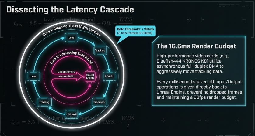
Glass-to-Glass (G2G) Latency: This measures the total, round-trip time required for a physical event to occur in front of the lens, be captured by the tracking system, calculated by the render engine, output by the video card, routed through the LED processor, and finally emitted as photons by the LED wall Bluefish444. G2G is typically a multi-frame measurement, commonly taking between 3 to 5 frames (equivalent to 125ms to 200ms at 24fps) Bluefish444. Research into immersive collaborative environments indicates that 150 milliseconds serves as a safe maximum target for end-to-end latency to maintain psychological immersion ResearchGate.
Milliseconds (MS) of Processing "Time Saved": This is a sub-frame measurement analyzing the efficiency of the Input/Output process Bluefish444. High-performance video cards, such as the Bluefish444 KRONOS K8, utilize asynchronous full-duplex Direct Memory Access (DMA) I/O engines to aggressively reduce the time required to move tracking data and frame buffers into the GPU Bluefish444. The time saved during this I/O process is directly translated into "time added" for the Unreal Engine to perform rendering Bluefish444. This is paramount; a game engine aiming for 60 frames per second has a rigid frame budget of 16.6 milliseconds Unity. If complex 3D geometry causes a frame to take 0.25 seconds to render, a massive stutter occurs Unity. MS time saved provides the engine with crucial milliseconds to stabilize performance and prevent dropped frames Bluefish444.
Genlock Protocols and Advanced Frame-Syncing Architectures
To enforce absolute synchronicity across this complex pipeline, every piece of hardware in the studio must be tethered to a Sync Pulse Generator (SPG) ROE Visual. Without genlock, free-running components will eventually drift out of phase, leading to dropped frames, multiplexing flicker, and tearing ROE Visual.
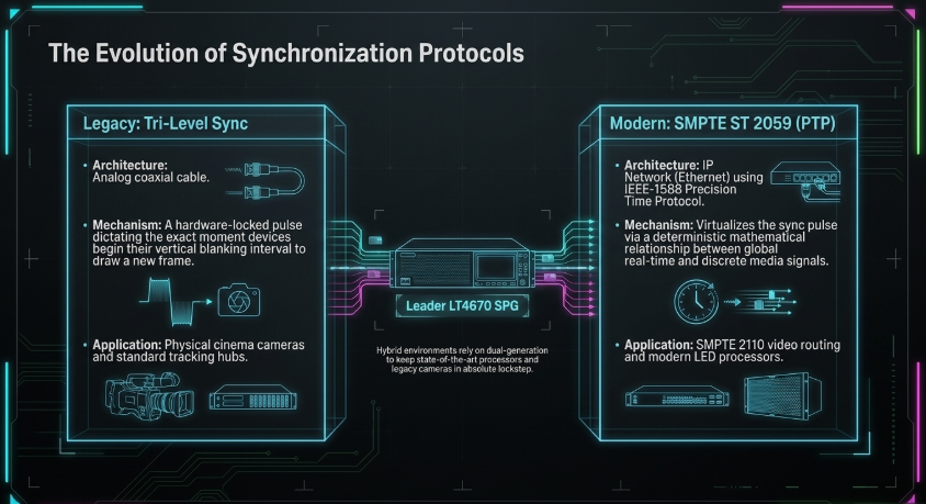
Historically, broadcast synchronization relied on analog Blackburst or Tri-Level Sync signals distributed via dedicated coaxial cables Leader Phabrix. Tri-Level Sync provides a highly accurate, legacy analog pulse that dictates the exact moment all connected devices must begin their vertical blanking interval and draw a new frame JEM Productions.
However, modern ICVFX pipelines are increasingly migrating toward high-bandwidth, IP-based infrastructures. The SMPTE ST 2059 standard suite provides a method to accommodate all reference and media signals using the IEEE-1588 Precision Time Protocol (PTP), delivered directly over an IP network Leader Phabrix. ST 2059 establishes a deterministic mathematical relationship between global real-time and discrete media signals, effectively virtualizing the physical sync pulse YouTube. This protocol is mission-critical for modern IP video standards like SMPTE 2110, which Unreal Engine 5.4 utilizes to multicast render nodes directly to LED processors SMPTE.
PTP networks require meticulous architectural design. In advanced setups, the distribution network is segregated into a dedicated VLAN hosted on PTP-capable switches operating in Transparent Clock (TC) mode, often utilizing spine-and-leaf topologies (Spine Blue/Spine Red) linked with high-speed fiber to minimize transmission delay SMPTE. Furthermore, hardware like the Leader LT4670 SPG acts as a critical bridge in hybrid environments, simultaneously generating both legacy Tri-Level Sync and ST 2059 PTP signals Leader Phabrix. This ensures that older cinematic cameras and state-of-the-art LED processors remain in absolute lockstep Leader Phabrix. The LT4670 also features mechanisms for "slow syncing" during GPS reference loss, gradually steering the system clock rather than applying abrupt corrections, which prevents catastrophic video and audio disruptions during live broadcasts Leader Phabrix.
Sub-Framing Technologies: Multiplexing the Visual Reality
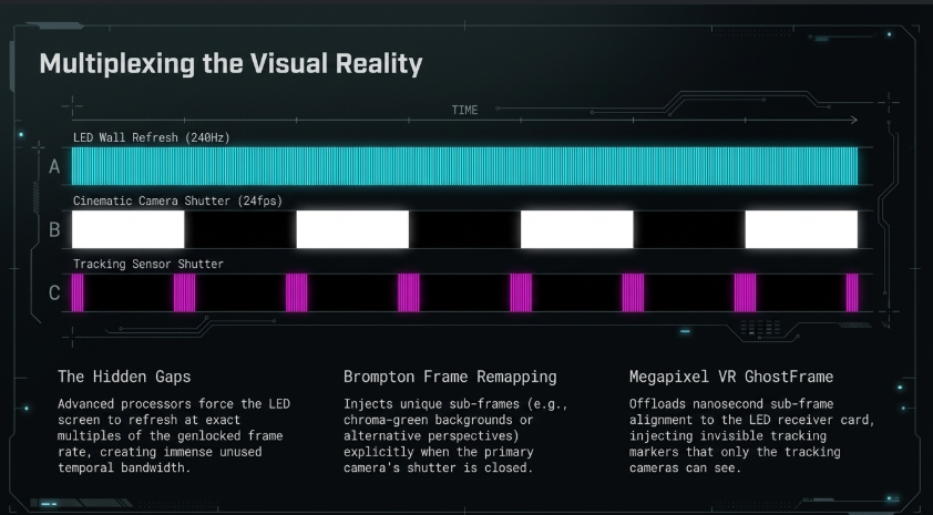
The integration of robust Genlock protocols has enabled LED processor manufacturers to manipulate the refresh cycle of the display at the sub-frame level. Because top-tier LED panels from manufacturers like ROE Visual can refresh at rates up to 240Hz, a standard cinematic camera operating at 24fps leaves an immense amount of temporal bandwidth completely unused Brompton Technology. Advanced processing technologies, such as Brompton Technology's Frame Remapping and Megapixel VR's GhostFrame, exploit this temporal gap to completely revolutionize on-set workflows Brompton Technology.
Brompton Frame Remapping
Brompton's Tessera processors (specifically the SX40 and S8) utilize a feature termed Frame Rate Multiplication, forcing the LED screen to refresh at an exact multiple of the genlocked input frame rate Brompton Technology. The Frame Remapping technology extends this by permitting operators to specify distinct, unique video content for each interleaved sub-frame Brompton Technology.
For example, if two cameras are genlocked to the same SPG but configured with an intentional phase offset, Camera A's shutter can open to capture the primary 3D Unreal Engine background, while Camera B's shutter opens microseconds later to capture a completely different rendered perspective or a solid chroma-green background Brompton Technology. To the naked eye of the crew on set, the LED wall appears to display a chaotic, superimposed blur of both video feeds, but the perfectly genlocked global shutters of the cameras extract only their specifically assigned sub-frames Brompton Technology. This allows for complex multi-camera shoots within a single volume without the perspectives shattering Brompton Technology.
Megapixel VR GhostFrame
Megapixel VR's GhostFrame technology pushes sub-framing even further. While Brompton generates the sub-frames natively on the main processor unit (which increases data load on the distribution network), the GhostFrame architecture offloads much of the sub-framing calculation directly to the receiver card located inside the LED panel itself ROE Visual.
Compatible exclusively with the HELIOS LED Processing Platform and ROE Visual LED panels, GhostFrame achieves sub-frame alignment at the nanosecond level Megapixel VR. This allows production teams to simultaneously capture up to four unique video feeds, embed invisible tracking markers, and project chroma key backgrounds all within a single cinematic take, without adding any hardware latency to the pipeline Megapixel VR. The ability to capture the final in-camera visual effect alongside a clean green-screen matte provides an invaluable safety net for post-production compositors ROE Visual.
Crucially, both Brompton and Megapixel VR utilize sub-framing to solve the issue of optical tracking in an LED volume ROE Visual. Traditional tracking systems require reflective markers on the ceiling, but in modern volumes, the ceiling is composed of emissive LED screens Brompton Technology. By interleaving a sub-frame containing high-contrast digital tracking markers (dots or crosses) exclusively during the fractional millisecond when the cinema camera's shutter is closed, the tracking cameras can continuously read the markers without them ever bleeding into the principal photography ROE Visual.
Camera-Tracking Technologies and Spatial Accuracy
If the virtual frustum is to respond accurately to the physical camera's movement, the tracking system must provide real-time, six degrees of freedom (6DoF) data-measuring the camera's X, Y, and Z positional coordinates, alongside its Pitch, Yaw, and Roll rotational axes OptiTrack. The virtual production industry relies predominantly on two distinct architectural paradigms to achieve this: "Inside-Out" optical tracking and "Outside-In" volumetric tracking.
Inside-Out Optical Tracking: Mo-Sys StarTracker
Inside-out tracking systems utilize a dedicated optical sensor mounted directly onto the cinematic camera body. This sensor looks outward into the physical studio environment to calculate its spatial position relative to known anchor points. The established industry standard for this architecture is the Mo-Sys StarTracker KST Moschkau.
The StarTracker system features a compact, upward-facing infrared (IR) camera equipped with a ring of IR illuminators KST Moschkau. This sensor maps a constellation of retro-reflective stickers ("stars") affixed randomly to the studio ceiling KST Moschkau. The initial calibration involves a brief mapping walk where the system calculates the exact 3D coordinates of these stars Mo-Sys. Because the StarTracker constantly references this absolute, fixed physical map, it operates completely free of the mechanical drift that plagues encoded camera pedestals, which rely on dead-reckoning and accumulate positional error over time Mo-Sys.
When integrating the StarTracker into a fully enclosed LED volume where physical stickers cannot be used on an LED ceiling, the system integrates tightly with Brompton Tessera processors to generate "digital stars" Brompton Technology. The Tessera processor injects small, high-contrast dots directly into the LED ceiling's video feed Brompton Technology. Utilizing Frame Remapping, these digital stars are flashed exclusively during the camera's shutter-closed period Brompton Technology. To accommodate this, the physical Mo-Sys sensor must have its native IR filter removed (or swapped for a blue filter) so it can detect the visible light spectrum emitted by the LEDs, and its sensor exposure is tuned meticulously (typically between 0.1 and 1.0 milliseconds) to read the sub-frame Brompton Technology.
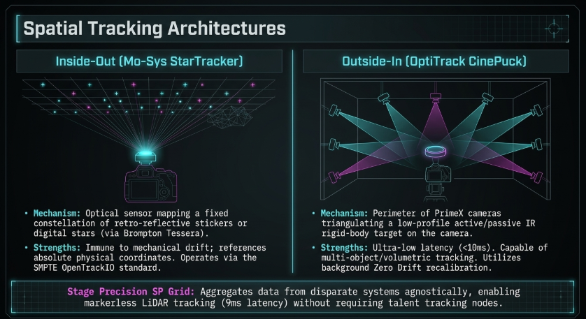
Mo-Sys is also deeply involved in standardizing tracking data transport. While older systems relied on the FreeD protocol, Mo-Sys has spearheaded the SMPTE OpenTrackIO standard Mo-Sys. OpenTrackIO is a first-of-its-kind open-source C++ library that establishes a unified format for tracking precision, sub-frame synchronization, and dynamic lens distortion data, radically improving the reliability of data ingested by Unreal Engine Mo-Sys.
Outside-In Volumetric Tracking: OptiTrack CinePuck
Outside-in tracking systems invert the spatial architecture: a perimeter of fixed, high-speed tracking cameras looks inward at a target attached to the moving cinematic camera OptiTrack. OptiTrack dominates this space, utilizing an array of PrimeX cameras rigidly mounted to the studio grid OptiTrack.
The cinematic camera is equipped with an OptiTrack CinePuck-a low-profile, rigid-body target featuring wide-angle active or passive IR LEDs OptiTrack. The PrimeX cameras flood the volume with infrared light (or detect the active pulses from the puck) and triangulate the CinePuck's exact 3D position at incredibly high refresh rates OptiTrack.
OptiTrack systems are engineered for ultra-low latency, operating with an end-to-end system delay of less than 10 milliseconds OptiTrack. The system boasts extraordinary spatial precision, offering positional accuracies of $\pm0.2$ mm and rotational accuracies of $\pm0.1^{\circ}$ OptiTrack. The core Motive software platform utilizes "Zero Drift" technology, which continually and automatically recalibrates the tracking volume during normal operation OptiTrack. This background process compensates for microscopic shifts in the physical environment caused by temperature fluctuations or building vibrations, ensuring a persistently fresh calibration OptiTrack.
To guarantee absolute temporal synchronicity, the OptiTrack ecosystem routes through the eSync 2 hardware hub, which locks the tracking cameras to external Genlock or SMPTE Timecode OptiTrack. This ensures that the positional data packet dispatched to the rendering engine is stamped with the exact same temporal metadata as the video frame captured by the cinematic camera OptiTrack. While outside-in systems provide unmatched accuracy and the ability to track multiple objects simultaneously (such as props and talent), they are susceptible to occlusion; if an actor blocks the line of sight between the CinePuck and the perimeter cameras, data can be momentarily compromised, though OptiTrack's 6DoF algorithms are designed to maintain accurate trajectory even if only a single marker remains visible OptiTrack.
Aggregation and Markerless Tracking: Stage Precision SP Grid
Managing disparate tracking systems, genlock statuses, and lens data can overwhelm production operators. To solve this, studios employ tracking aggregation software, with Stage Precision's SP Grid platform leading the sector Stage Precision. SP Grid acts as a central control hub, ingesting tracking data from almost any system-from Mo-Sys to FreeD and OptiTrack-and routing it agnostically to the rendering engine Stage Precision.
Furthermore, SP Grid enables markerless tracking. By integrating technologies like AR-51 skeleton data or RoboSense 3D LIDAR spatial sensing, the system can identify specific individuals by appearance and track their position with a latency of just 9 milliseconds, without requiring the talent to wear any tracking nodes or reflective suits. This data can then trigger automated lighting states, PTZ camera movements, or content shifts within the Unreal Engine environment Stage Precision.
Lens Calibration, Nodal Offset, and Unreal Engine Integration
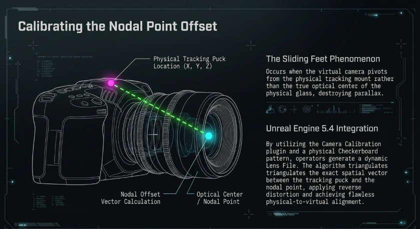
Capturing sub-millimeter 6DoF tracking data is fundamentally useless if the virtual camera inside Unreal Engine does not perfectly replicate the optical characteristics of the physical lens attached to the camera. Even the most expensive, hand-crafted cinema lenses exhibit unique optical distortions, and their exact optical center-the nodal point-shifts dramatically depending on the focal length and the focus distance Unreal Engine. Failing to accurately map these variables leads to the dreaded "sliding feet" phenomenon, where virtual background objects appear to drift or float relative to the physical foreground as the camera pans or tilts.
The Camera Calibration Plugin and Lens Files
In Unreal Engine 5.4 and beyond, the alignment of physical and virtual optics is managed through the Camera Calibration plugin and the creation of a precise Lens File asset Unreal Engine. The Lens File acts as an intricate mathematical repository, storing parameters such as focal length, iris mapping, the optical center offset ($F_{x}$, $F_{y}$), and complex radial and tangential distortion coefficients (e.g., $K_{1}$, $K_{2}$, $P_{1}$, $P_{2}$) Unreal Engine.
Because modern zoom lenses change their optical properties non-linearly across their focal range, a high-quality calibration requires mapping the lens at multiple focus and zoom demarcations Unreal Engine. To achieve this, the Camera Calibration plugin relies on an automated computer vision process. The physical camera is positioned facing a rigidly mounted Checkerboard pattern of exact, known dimensions Sean W Adair. As the operator moves the camera around the checkerboard, capturing various angles, tilts, and perspectives, Unreal Engine (or specialized third-party tools like Kalibrate) analyzes the physical bowing, curvature, and chromatic aberration of the straight lines on the checkerboard Sean W Adair.
The system then generates a reverse distortion algorithm. This algorithm is applied as an accurate post-process effect directly to the CineCamera Actor within Unreal Engine, mathematically warping the rendered 3D background to match the exact physical distortion of the physical cinema lens Unreal Engine. This ensures that when the physical camera views a straight pillar in the virtual world, it actually appears straight through the distorted physical lens. Tools like Kalibrate streamline this by instantly computing the parameters from captured images and exporting a JSON file that is converted into Unreal Engine lens and camera assets via Python scripts, automating a previously tedious task Sean W Adair.
Calibrating the Nodal Point Offset
The tracking hardware-whether a CinePuck or a StarTracker-is physically mounted to the exterior chassis of the camera body. Therefore, the origin point of the tracking data is offset from the optical center (nodal point) of the lens by several inches in the X, Y, and Z axes. This spatial discrepancy, known as the nodal offset, must be calculated with extreme precision to ensure the pivot point of the virtual camera matches the pivot point of the physical glass Epic Developer Community Forums.
In Unreal Engine, this calibration is executed using the Nodal Offset Points Method Unreal Engine. An active tracking marker-such as a Vive tracker, an OptiTrack probe, or a printed AprilTag/Aruco marker using a system like RETracker Bliss-is placed rigidly in the physical space. The physical camera aims directly at the tracker, and the operator captures the location. The camera is then pivoted on its tripod and moved to capture the exact same tracker from multiple different angles. By comparing the known coordinates of the tracker in physical space with how that tracker projects through the previously calibrated, distorted lens onto the 2D sensor plane, Unreal Engine's algorithms triangulate the exact spatial vector between the physical tracking mount and the optical center of the lens Unreal Engine.
This calculated vector is then saved to the Lens File Unreal Engine. Consequently, when the tracking puck moves forward exactly one inch, the system knows to move the virtual camera's nodal point exactly one inch along the correct trajectory, completely eliminating slippage and maintaining perfect parallax alignment between the real and virtual worlds Unreal Engine. Recent updates in Unreal Engine 5.4 have further refined this process, allowing the system to solve for both Lens Distortion and Nodal Offset simultaneously, drastically speeding up the calibration workflow for the operator while minimizing reprojection errors Epic Developer Community Forums.
nDisplay Topology and Inner Frustum Rendering
Once the tracking is stable, the lens is calibrated, and the physical parameters are set, the final hurdle is efficiently rendering the high-fidelity graphical data and delivering it to the LED processors without inducing visual latency. This routing is managed by nDisplay, Epic Games' architecture for distributing real-time renders across multiple GPUs and PCs to drive massive, synchronized LED canvases Epic Developer Community.
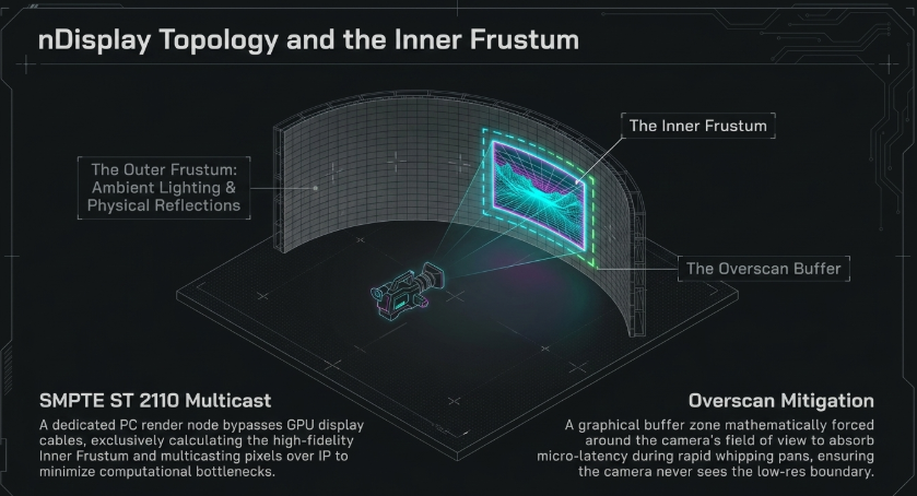
In a traditional ICVFX setup, the nDisplay cluster outputs a static, pre-rendered, or low-resolution version of the 3D environment onto the entirety of the LED wall-this is known as the outer frustum Epic Developer Community. The primary function of the outer frustum is to provide accurate ambient lighting and physical reflections onto the actors and props on the stage Unreal Engine.
Simultaneously, the system calculates the exact perspective of the tracked CineCamera Actor and renders a high-resolution, distortion-corrected patch of the 3D environment-the inner frustum-directly behind the physical subjects, precisely where the physical camera's lens is looking Epic Developer Community. As the physical camera moves, pans, or tilts, the inner frustum rapidly tracks with it in real-time across the physical LEDs Brompton Technology.
However, rendering both the massive outer frustum and the highly detailed inner frustum on a single PC node creates severe computational bottlenecks, increasing frame times and thereby increasing end-to-end latency Epic Developer Community. To mitigate this, Unreal Engine 5.4 introduced advanced ICVFX camera streaming utilizing the SMPTE ST 2110 protocol Epic Developer Community.
By leveraging ST 2110's multicast capabilities, studios can now design an nDisplay topology where a dedicated render node PC is assigned exclusively to rendering the high-fidelity inner frustum of the tracked camera Epic Developer Community. Once rendered, these pixels are transported over the IP network directly to the composer nodes or the LED processors, completely bypassing physical GPU display cables Epic Developer Community. This dramatically scales the system's efficiency and minimizes latency Epic Developer Community.
Even with optimized networks, slight delays can occur during rapid, whipping camera pans. Because the camera moves faster than the frames can be drawn and transmitted, the edge of the inner frustum can temporarily bleed into the low-resolution outer frustum Unreal Engine Forums. Operators mitigate this by applying horizontal or uniform overscan within the nDisplay Render Queue settings Unreal Engine Forums. Overscan forces the engine to render a slightly larger frustum than the camera's actual field of view, creating a graphical buffer zone that absorbs the micro-latency of rapid movement, ensuring the physical camera never sees beyond the high-resolution render patch Unreal Engine Forums.
Conclusion
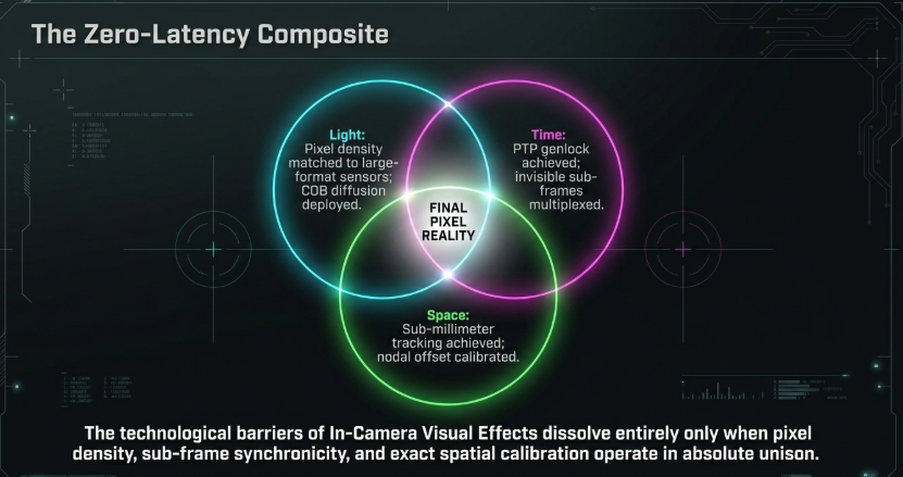
The successful execution of In-Camera Visual Effects within an LED volume represents the pinnacle of modern broadcast and cinematic engineering. Achieving a final-pixel, zero-latency composite requires mastering a highly interconnected, fragile web of optical, temporal, and spatial technologies. The persistent threat of moiré interference cannot be resolved by a singular piece of hardware; it is a holistic calculation that demands aligning the physical pixel pitch of the LED wall-optimally positioned between 1.5mm and 2.3mm for close proximity-with the Nyquist limits of large-format camera sensors. This is further mitigated by exploiting the optical physics of shallow depth of field, deploying sophisticated internal Optical Low-Pass Filters, and leveraging advanced Chip-on-Board LED encapsulation architectures that naturally diffuse geometric grid interference.
Equally critical is the management of temporal latency and frame multiplexing. The transition from legacy analog sync to IP-based SMPTE ST 2059 (PTP) protocols has unified the temporal clock of disparate cameras, rendering engines, and tracking hardware into a cohesive network. Advanced sub-framing technologies, such as Brompton's Frame Remapping and Megapixel VR's GhostFrame, capitalize on highly multiplexed LED refresh rates to interleave hidden tracking markers and multiple visual perspectives within a single frame, operating entirely outside the temporal perception of the physical camera's shutter.
Finally, the realization of true parallax and immersive depth hinges on flawless spatial tracking and calibration. Whether a production utilizes the inside-out mapping of the Mo-Sys StarTracker or the ultra-low latency, volumetric precision of the OptiTrack CinePuck, positional data must reach the engine in under 10 milliseconds. Yet, this spatial data is functionally irrelevant without rigorous optical alignment. By accurately calculating dynamic lens distortion and triangulating the exact nodal offset via Unreal Engine's Camera Calibration plugin, the virtual camera flawlessly mimics the specific imperfections of its physical counterpart. When pixel density, sub-frame synchronicity, and exact spatial calibration operate in absolute unison, the technological barriers dissolve entirely, resulting in a seamless, artifact-free integration between physical reality and real-time digital rendering.