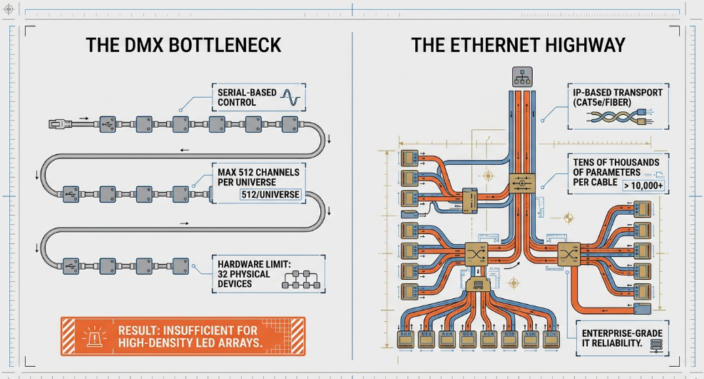
The contemporary transition within large-scale studio facilities from traditional serial-based control to high-capacity Internet Protocol (IP) networks represents one of the most significant paradigm shifts in entertainment technology. As production requirements scale to include tens of thousands of parameters—often driven by high-density LED pixel arrays, complex architectural elements, and multi-layered performance rigs—the inherent limitations of the legacy DMX512-A standard have become insurmountable. A single DMX512 universe, limited to 512 channels and a maximum of 32 physical devices on a single daisy-chain, cannot accommodate the data density required for modern volumetric capture or large-scale broadcast environments. To address these challenges, integrators now deploy sophisticated Ethernet-based protocols, primarily Art-Net and Streaming ACN (SACN), over managed IT infrastructure to provide the necessary bandwidth, flexibility, and reliability.
The Evolution of Ethernet-Based Lighting Transport
The foundational objective of moving lighting control to Ethernet was to leverage existing, cost-effective IT infrastructure to transport multiple universes of DMX data over a single physical cable. This approach replaces bundles of expensive, specialized XLR cabling with high-speed copper (CAT5e/CAT6) or fiber optics capable of transporting thousands of universes simultaneously (Sundrax).
Art-Net 4 Architecture and Logical Addressing
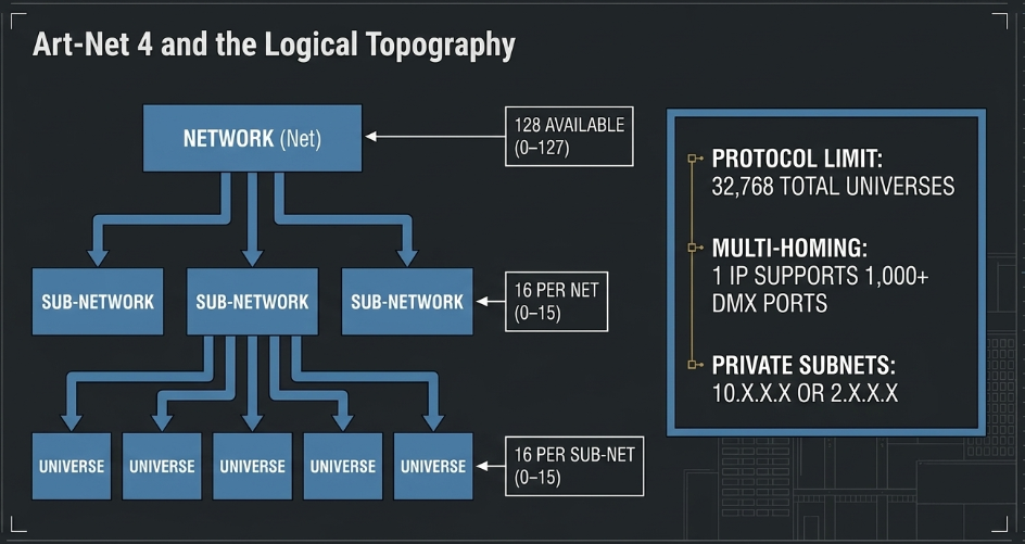
Art-Net, initially developed by Artistic Licence in 1998, has undergone four major revisions to maintain its relevance as lighting systems grew in complexity. The original Art-Net I relied heavily on broadcast transmission, which effectively capped its scalability at approximately 40 universes before the resulting network traffic overwhelmed receiving nodes. Art-Net II and III introduced unicast capabilities and expanded the universe limit, while Art-Net 4, released in 2016, solved the "multi-homing" challenge, allowing a single IP address to support over 1,000 DMX ports through advanced gateway management (Sundrax).
The addressing logic of Art-Net 4 is built upon a hierarchical structure known as Net.Sub-Net.Universe. This scheme allows for the logical organization of up to 32,768 unique universes. A "Net" represents a group of 256 universes; there are 128 available Nets. Each Net is divided into 16 Sub-Nets, and each Sub-Net contains 16 Universes. This structure is essential for integrators when planning the logical topography of a large studio.
Art-Net typically operates on private network ranges, traditionally 2.x.x.x/8 or 10.x.x.x/8, though modern managed networks often utilize the 192.168.x.x/24 space for smaller localized segments. In an Art-Net 4 environment, the protocol handles DMX and RDM (Remote Device Management) data, enabling bi-directional communication for fixture configuration and health monitoring (Sundrax).
Streaming ACN (SACN) and the ANSI E1.31 Standard
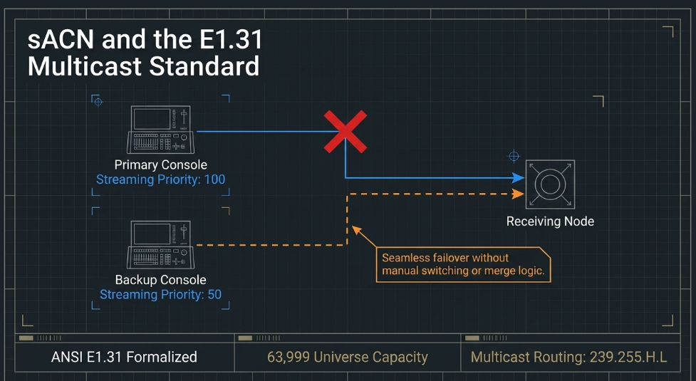
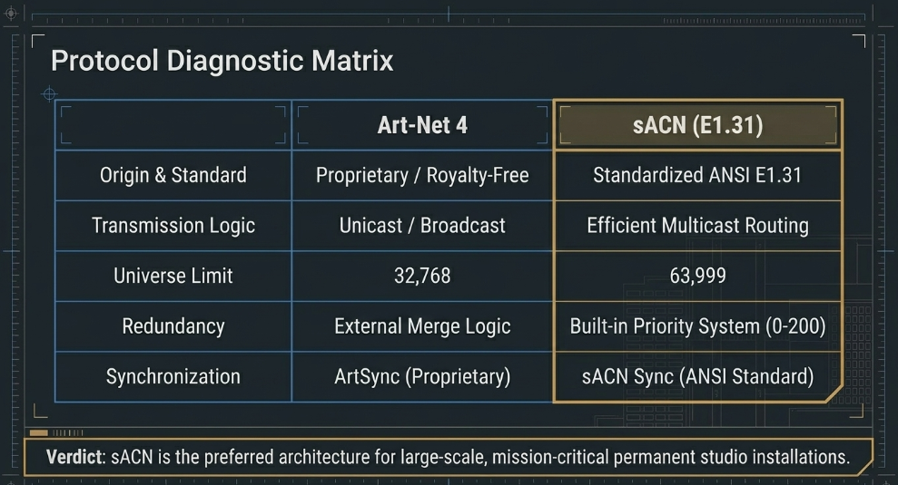
Streaming ACN (SACN), formalized as ANSI E1.31, is the industry's preferred choice for high-reliability, large-scale permanent installations and mission-critical live events. Unlike Art-Net, which began as a proprietary (though royalty-free) protocol, sACN is a standardized lightweight version of the more complex Architecture for Control Networks (ACN). The protocol was specifically architected to support efficient data delivery over modern IP networks through the use of multicast transmission.
The fundamental strength of sACN lies in its ability to support up to 63,999 universes, nearly double that of Art-Net 4. Each universe is mapped to a unique multicast IP address in the range of 239.255.x.y, where x and y represent the high and low bytes of the universe number. This allows network switches to forward data only to the ports that have actively requested it, preserving overall network bandwidth and reducing the processing load on lighting nodes (Newfeel Laser).
A critical differentiator for SACN is its integrated priority system. Every sACN packet contains a priority value between 0 and 200, with 100 being the standard default. If a receiving node detects multiple sources for the same universe, it will automatically listen to the source with the highest priority. This enables sophisticated redundancy schemes where a primary and backup console can both be active on the network simultaneously; if the primary (set at priority 100) fails, the backup (set at priority 90) seamlessly takes control without the need for manual switching or complex merge logic (Sundrax).
Managed Switching Infrastructure for High-Density Data
The successful deployment of a high-parameter lighting rig is entirely dependent on the performance of the underlying network hardware. Professional integrators moving beyond a handful of universes must move away from unmanaged consumer-grade hardware toward managed Layer 2 and Layer 3 switches. Lighting control traffic, while low in raw bandwidth compared to video, is highly "bursty" and time-sensitive, requiring specific switch features to ensure stability (Advatek).
Backplane Bandwidth and Non-Blocking Performance
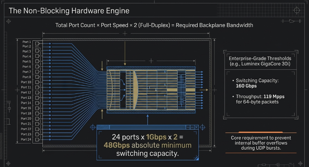
A switch's backplane bandwidth, also known as its switching capacity, represents the maximum amount of data the device can process internally between its ports (Optcore). For a lighting network to be considered "wire-speed" or "non-blocking," the backplane must be capable of handling the theoretical maximum load of all ports simultaneously (Optcore).
For example, a 24-port Gigabit switch must have a switching capacity of at least 48 Gbps to ensure that all ports can operate at their full 1 Gbps rate in full-duplex mode without internal bottlenecks (Optcore). The calculation follows: Total Port Count x Port Speed x 2 (Full-Duplex) = Required Backplane Bandwidth (Optcore)
Hardware like the Luminex GigaCore 30i is engineered specifically for these demands, offering a switching capacity of up to 168 Gbps and a throughput of 125 Mpps (Million Packets Per Second) for 64-byte packets (Luminex). This ensures that the massive surge of UDP packets generated by 1,000+ universes at the start of every frame does not cause internal buffer overflows (Extreme Networks).
Packet Buffer Architectures: SRAM vs. DRAM
In high-density lighting applications, specifically those involving pixel mapping and rapid effects, the architecture of a switch's packet buffer is more important than its raw bandwidth (Extreme Networks). When multiple input ports send data to a single output port simultaneously (incast congestion), the switch must buffer those packets until they can be egressed (NVIDIA).
There are two primary buffer designs found in enterprise switches:
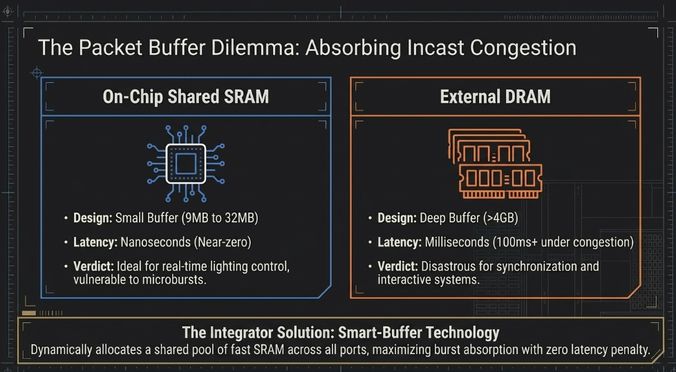
On-Chip Shared SRAM (Small Buffer): This architecture provides very low latency (measured in nanoseconds) but has limited memory capacity, typically around 12 MB to 16 MB (Broadcom). In a lighting environment, these are ideal for low-latency control but may drop packets during massive microbursts from a media server (Broadcom).
External DRAM (Deep Buffer): These switches utilize large external memory pools, often exceeding 100 MB, to absorb significant bursts (NVIDIA). However, deep buffers introduce substantial latency (up to 20 milliseconds or more under congestion), which can be disastrous for lighting synchronization and real-time interactive systems (NVIDIA).
Most professional lighting integrators prefer switches with "Smart-Buffer" technology, such as the Broadcom StrataXGS or Nvidia Spectrum families, which dynamically allocate a shared pool of fast SRAM across all ports to maximize burst absorption without the latency penalty of DRAM (Extreme Networks).
Advanced Multicast Configuration and IGMP Logic
Managing tens of thousands of parameters requires the precise configuration of the Internet Group Management Protocol (IGMP) to prevent the network from being inundated with unnecessary traffic. While unicast Art-Net is simple to deploy, it lacks the efficiency of sACN's multicast model for large systems (DMX Guide).
The Mechanics of IGMP Snooping
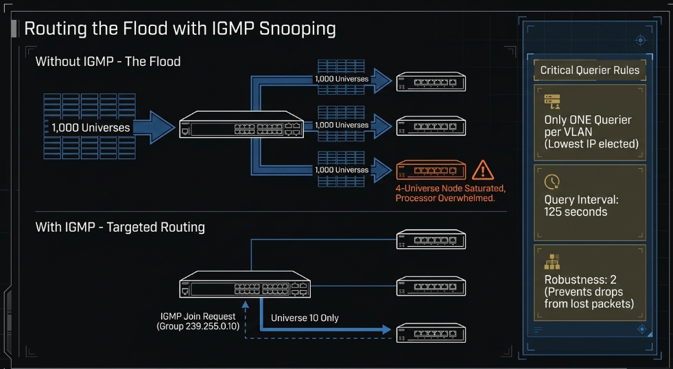
Without IGMP Snooping, a Layer 2 switch treats multicast traffic exactly like broadcast traffic, sending every universe to every single port on the VLAN (Advatek). For a lighting node designed to handle only 4 universes, receiving a stream of 1,000 universes will saturate its processor, leading to erratic light behavior and frequent disconnects (Sundrax).
IGMP Snooping allows the switch to "snoop" on the membership reports sent by lighting nodes (Advatek). When a node on Port 5 sends an IGMP Join for Universe 10 (multicast group 239.255.0.10), the switch updates its internal forwarding table to route that specific group only to Port 5 (Singularity). This ensures that each node only receives the data it actually requires to drive its connected fixtures (Advatek).
IGMP Querier Election and Robustness
For IGMP Snooping to persist, the network requires an IGMP Querier (Enttec). The Querier is a designated device (typically the core switch) that periodically sends "General Membership Queries" to all devices to verify they still want to receive their subscribed streams (ETC). If the switch does not hear a response from a node within a set timeout period, it will stop forwarding that multicast group to that port (ETC).
Best practices for Querier configuration in a professional lighting rig include:
Single Querier per VLAN: Only one device must be active as the Querier to prevent network instability. If multiple switches are capable, the one with the lowest IP address is typically elected as the master (ETC).
Query Interval Calibration: The Query Interval (time between queries) should be set appropriately (e.g., 30 to 60 seconds) to balance network overhead with the need for rapid membership updates (ETC).
Querier Robustness: This value determines how many query packets are sent in each transmission. In high-interference environments, a higher robustness count (e.g., 2 or 3) ensures that a single lost packet does not cause a node to be dropped from its universe subscription (ETC).
Convergence and Temporal Integrity
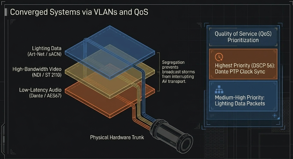
In large-scale studio facilities, the lighting network does not exist in isolation. Modern production environments increasingly utilize converged networks where lighting data (Art-Net/sACN) coexists with high-bandwidth video (NDI/SMPTE 2110) and low-latency audio (Dante/AES67) (Luminex). Maintaining temporal integrity across these disparate data types is one of the integrator's most complex challenges.
VLAN Segmentation and Quality of Service (QoS)
The primary tool for managing a converged network is logical segmentation via Virtual Local Area Networks (VLANs). By placing lighting, audio, and video on separate VLANs, integrators ensure that a broadcast storm or excessive multicast on the lighting segment does not interrupt critical audio or video transport (NDI Community).
However, VLANs alone do not solve the problem of physical link congestion on trunk lines between switches (NDI Community). This is where Quality of Service (QoS) becomes essential. QoS allows the switch to prioritize specific packets based on their DSCP (Differentiated Services Code Point) markings (Luminex). Dante audio, for example, requires PTP (Precision Time Protocol) packets to be given the highest possible priority (DSCP 56) to maintain clock synchronization (Symetrix). Lighting data is typically assigned a medium-high priority, ensuring it is processed ahead of general office traffic or management data (DMX Guide).
Precision Time Protocol (IEEE 1588) Integration
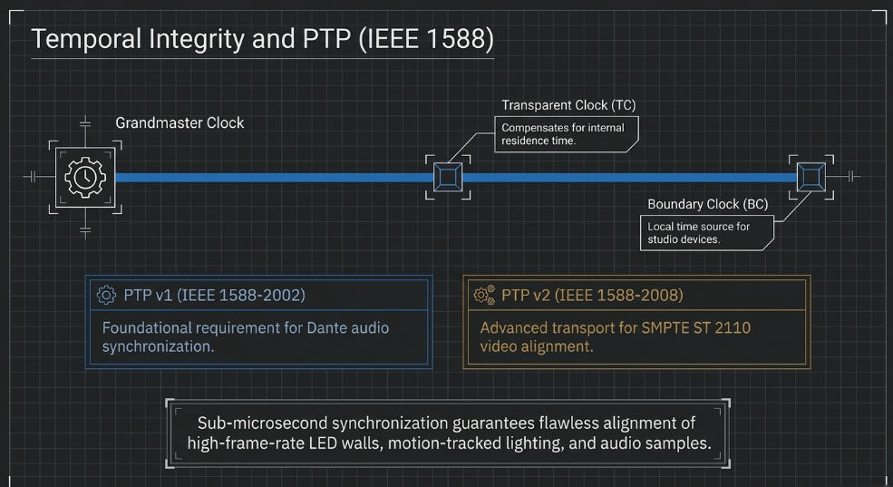
As studio demands move toward high-frame-rate LED walls and motion-tracked lighting, the need for sub-microsecond synchronization has led to the adoption of the Precision Time Protocol (PTP) (Luminex). PTP v1 (IEEE 1588-2002) is the foundational requirement for Dante, while PTP v2 (IEEE 1588-2008) is used for more advanced video transport like SMPTE ST 2110 (Luminex).
On a converged network, switches must be "PTP-aware" to prevent "jitter" caused by packet queuing (Luminex). A Transparent Clock (TC) switch modifies PTP messages to compensate for the time they spend inside the switch (residence time), while a Boundary Clock (BC) switch acts as its own high-precision clock, synchronizing its internal time to a Grandmaster and then serving as the time source for all connected devices (Luminex). Hardware like the Luminex GigaCore 30i supports these advanced clocking modes out-of-the-box, ensuring that lighting synchronization frames and audio sample clocks stay perfectly aligned (Luminex).
Redundancy, Resilience, and High Availability
In a professional studio, the cost of a network failure can be measured in thousands of dollars per minute of lost production time. Integrators implement multiple layers of physical and logical redundancy to create a "self-healing" network (Maple Systems).
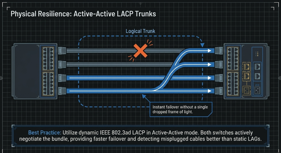
Link Aggregation (LAG) and LACP
Link Aggregation (LAG) allows multiple physical Ethernet cables between two switches to be combined into a single logical "trunk" (Maple Systems). This provides two key benefits: increased aggregate bandwidth and link-level redundancy (Maple Systems). If one cable in a 4-link bundle is severed, the network continues to operate on the remaining three links without any data loss or interruption to the lighting state (Maple Systems).
The Link Aggregation Control Protocol (LACP), defined in IEEE 802.3ad, is the dynamic standard used to manage these bundles (Maple Systems). Integrators prefer "Active-Active" LACP configurations, where both switches actively negotiate the bundle, as this provides faster failover and detects misconfigurations (such as a cable plugged into the wrong switch) that static LAGs cannot (MikroTik community forum).
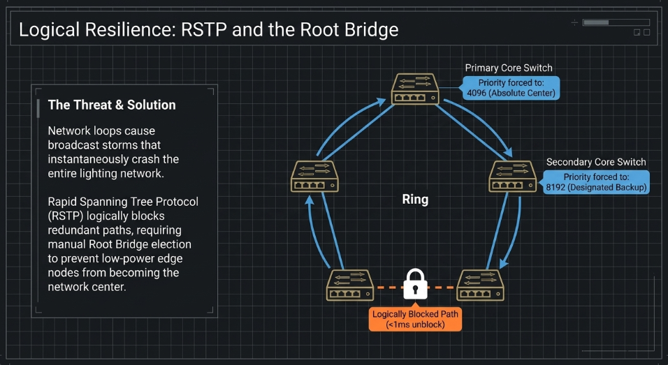
Rapid Spanning Tree Protocol (RSTP) and Topography Design
To prevent network loops while allowing for redundant physical paths, integrators utilize the Spanning Tree Protocol (STP), specifically its modern variant, Rapid STP (RSTP) (Maple Systems). In a "Star" or "Ring" topography, RSTP logically blocks one path to prevent data from endlessly circling the network (Maple Systems). If the primary link fails, RSTP unblocks the backup path in less than 300 milliseconds (Maple Systems).
Crucial for large studios is the manual configuration of the "STP Root Bridge" (Mylinking). If the Root Bridge is left to be elected automatically, the network might choose a low-power edge switch to be the center of the universe, leading to inefficient routing and potential congestion. Integrators manually set the priority of the main core switch to 0 (the highest priority) and the secondary core to 4096 to ensure the network always flows toward the most capable hardware (Ubiquiti).
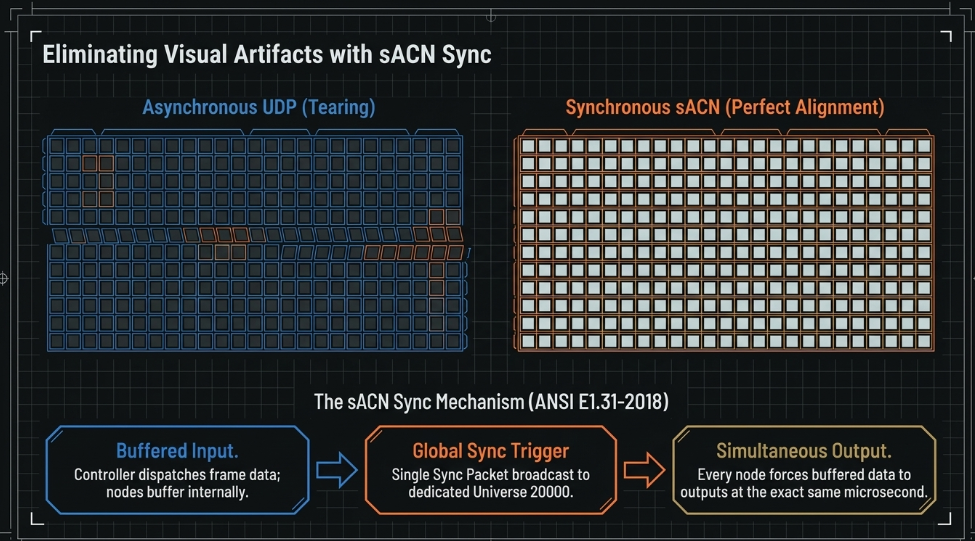
Preventing Visual Artifacts: sACN Sync and Tearing
As parameter counts reach the tens of thousands, often driving large-scale LED pixel walls or volumetric capture arrays, the phenomenon of "tearing" becomes a critical issue (Advatek). Tearing occurs when different lighting nodes output new DMX data at slightly different times, causing a visible "seam" or "jitter" across the display. This is inherently caused by the asynchronous nature of standard UDP/IP transport (Advatek).
The sACN Sync Packet (ANSI E1.31-2018)
The 2018 revision of the sACN standard introduced the "Synchronization Frame" to address this precise problem. The mechanism functions as follows:
Buffered Input: The lighting controller sends out all the DMX data packets for a specific frame, but nodes are instructed (via a flag in the packet header) to buffer this data rather than output it immediately (Advatek).
Global Sync Trigger: Once all data packets for the frame have been dispatched, the controller sends a single "Sync Packet" to a dedicated "Synchronization Universe" (Advatek).
Simultaneous Output: Every node on the network receiving this Sync Packet immediately pushes the buffered data to its physical outputs (Advatek).
This ensures that thousands of universes update at exactly the same microsecond, eliminating any visual tearing across massive LED façades or pixel-mapped surfaces (Advatek).
Strategic IP Addressing and Management Tools
The management of 10,000+ parameters often involves hundreds of individual nodes and gateways. Establishing a rigid and well-documented IP addressing strategy is a fundamental requirement for long-term stability and troubleshooting.
Static Addressing for Persistence
In professional lighting systems, static IP addresses are universally preferred over DHCP (Dynamic Host Configuration Protocol) for critical infrastructure. A static address ensures that nodes always reside at a known location, allowing consoles and media servers to reliably "unicast" data to them and providing technicians with immediate access to embedded web servers for diagnostics. Integrators typically segment their IP ranges by device type:
Orchestration Software: Araneo and Beyond
As the number of parameters increases, managing individual switches through their local web UIs or CLI (Command Line Interface) becomes inefficient. Advanced orchestration tools like Luminex Araneo provide a holistic view of the entire network topology (Luminex). Araneo allows integrators to visualize data flows in real-time, perform "Health Checks" on critical parameters, and push global configuration changes (like VLAN assignments or IGMP settings) across dozens of switches with a single click (Luminex). In offline mode, these tools enable the pre-planning of the entire network architecture before arriving on-site, significantly reducing commissioning time and the risk of configuration errors (Luminex).
Conclusion: Engineering for Scalability and Trust
Managing tens of thousands of lighting parameters over an IP network requires a comprehensive engineering approach that transcends basic IT practices. By deeply integrating the technical requirements of sACN and Art-Net 4 with the advanced features of managed switches—such as IGMP Snooping, non-blocking backplanes, and PTP-aware clocking—integrators can create lighting systems that are not only vast in scale but also indistinguishable from traditional DMX in terms of responsiveness and reliability.
The strategic use of sACN's multicast efficiency, combined with the logical isolation of VLANs and the physical protection of Link Aggregation, ensures that the studio's lighting backbone can handle the rigors of modern high-density production. As studios continue to evolve toward fully converged AV-over-IP architectures, the meticulous configuration of these protocols will remain the cornerstone of professional lighting integration.